Turbidimeter

a turbidimeter and turbidimeter technology, applied in the field of turbidimeters, can solve the problems of easy damage of turbidimeters, failure of light sources, scattered light detectors, transmitted light detectors, etc., and achieve the effect of simple and sturdy structure, reduced sealing positions, and reduced number of sealing positions

Active Publication Date: 2014-07-24
HORIBA ADVANCED TECHNO
View PDF12 Cites 13 Cited by
  • Summary
  • Abstract
  • Description
  • Claims
  • Application Information

AI Technical Summary

Benefits of technology

[0021]According to the present invention configured as described above, since the accommodating spaces for accommodating the light source and respective detectors are formed in the side wall of the sensor head made of an optically-transparent material and the inner surface of the side wall of the sensor head is used as the respective optical windows, the turbidimeter can be made with a simple and sturdy structure which is hard to break and sealing positions can be reduced in number. Therefore, it is possible to provide the turbidimeter which exhibits excellent long-term stability.

Problems solved by technology

However, in this turbidity sensor, since the light source, transmitted light detector, and scattered light detector are accommodated in a space formed between the sensor accommodating part and the measuring cell, the liquid sample infiltrates into the space due to factors such as deterioration of the sealing member in both end portions in the axial direction of the measuring cell, and this results in events such as a failure of the light source, transmitted light detector, and scattered light detector.
Moreover, it is necessary to assemble the measuring cell and sensor holding part via the sealing member, and therefore there is also a problem that not only does assembly become complicated, but also the turbidimeter is then easily damaged by an external impact.
Further, since the respective transparent windows and the main body portions other than the respective transparent windows in the measuring cell are composed of different materials, it is necessary to ensure sufficient sealing of these transparent windows and main body portions, and therefore a problem may likely arise that the sealing is degraded during a long period of use.
Therefore, not only does assembly become complicated, but there is also a concern that the transparent windows may be shifted by an impact from the outside.

Method used


Image

  • Turbidimeter
  • Turbidimeter
  • Turbidimeter

Examples


first embodiment

[0036]The following describes the first embodiment of a turbidimeter according to the present invention with reference to the accompanying drawings.

[0037]A turbidimeter 100 according to a first embodiment is an immersion (throwing-in) type that measures turbidity or suspended solid concentration (SS concentration) of treated water in a water treatment facility such as, for example, a sewage treatment plant, water purification plant, and the like, or measures turbidity or suspended solid concentration (SS concentration) of muddy water discharged from a construction site. In this turbidimeter 100, a measurement range is 0 to 1000 degrees (formazin, kaolin), 0 to 1000 mg / L (kaolin) and minimum resolution is 0.01 degree, 0.01 mg / L.

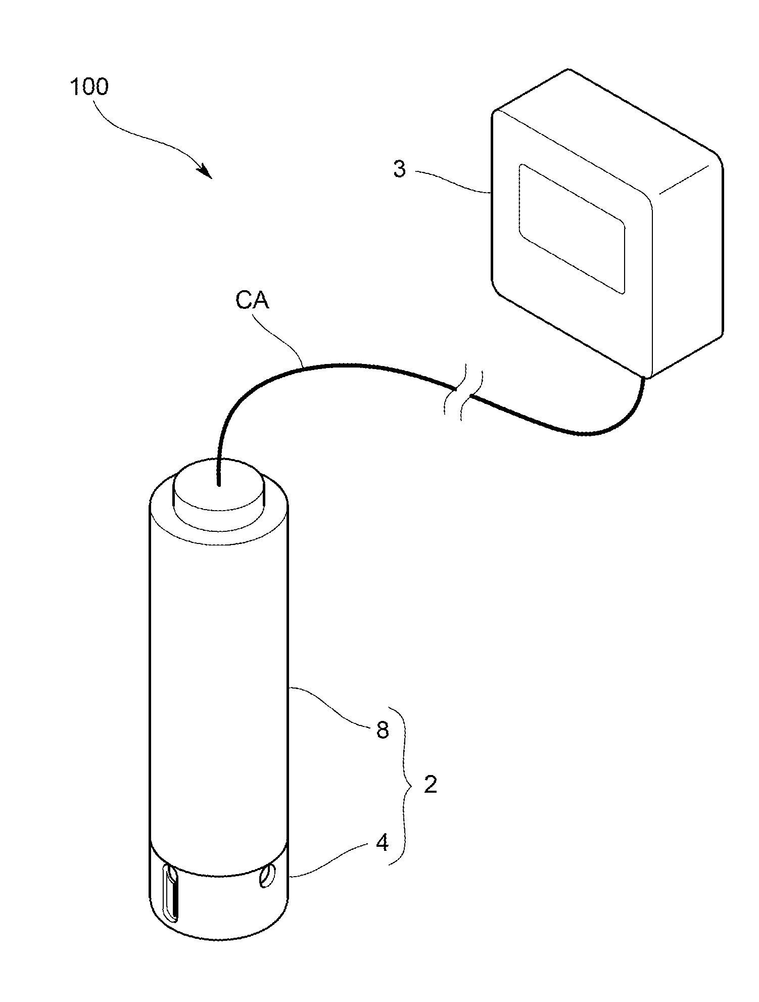
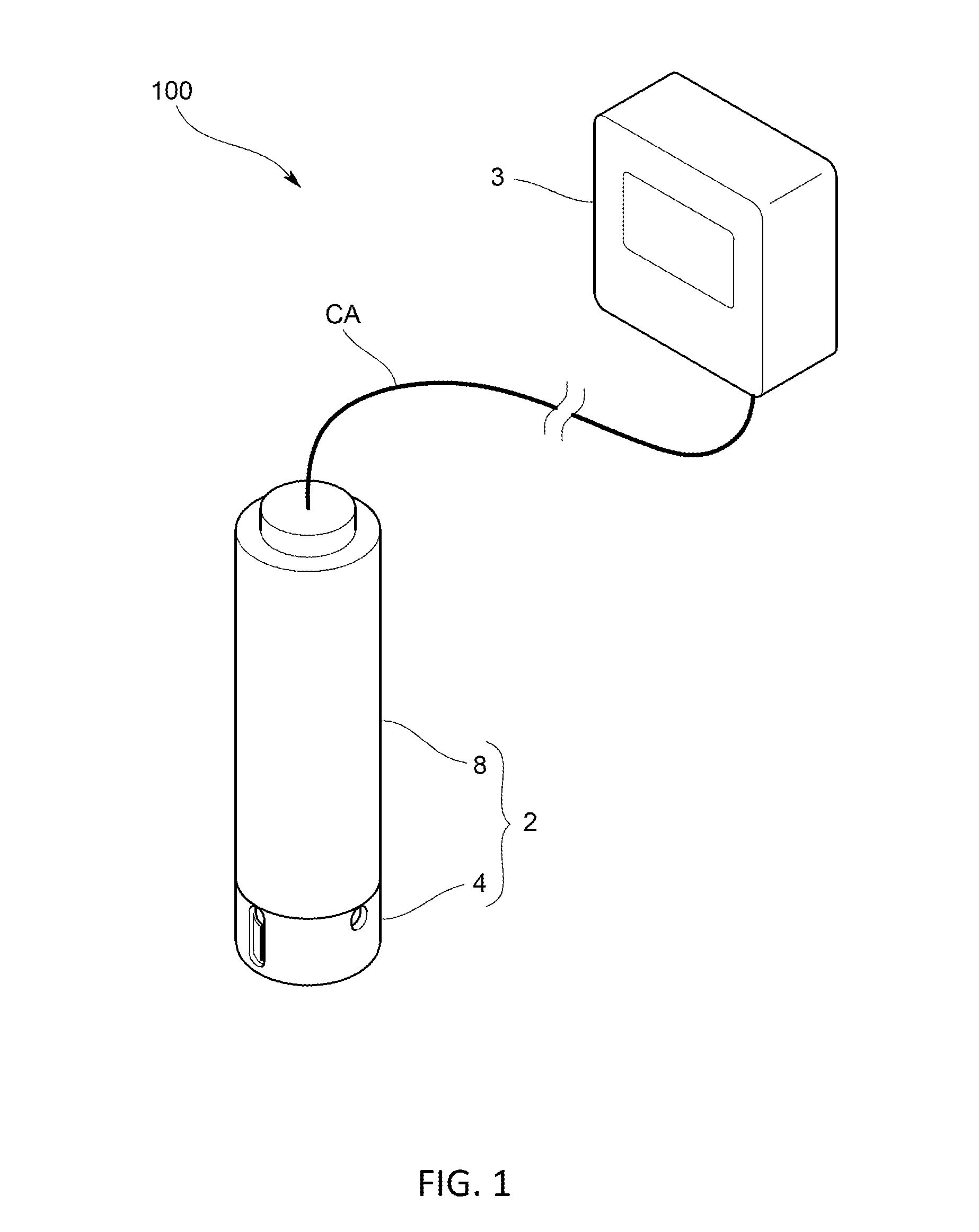
[0038]In specific, as shown in FIG. 1, the turbidimeter 100 includes an immersion type sensor main body 2 and a measuring instrument main body 3 which is electrically connected to the sensor main body 2 via a waterproof electrical cable CA.

[0039]As shown in FI...

second embodiment

Effect of Second Embodiment

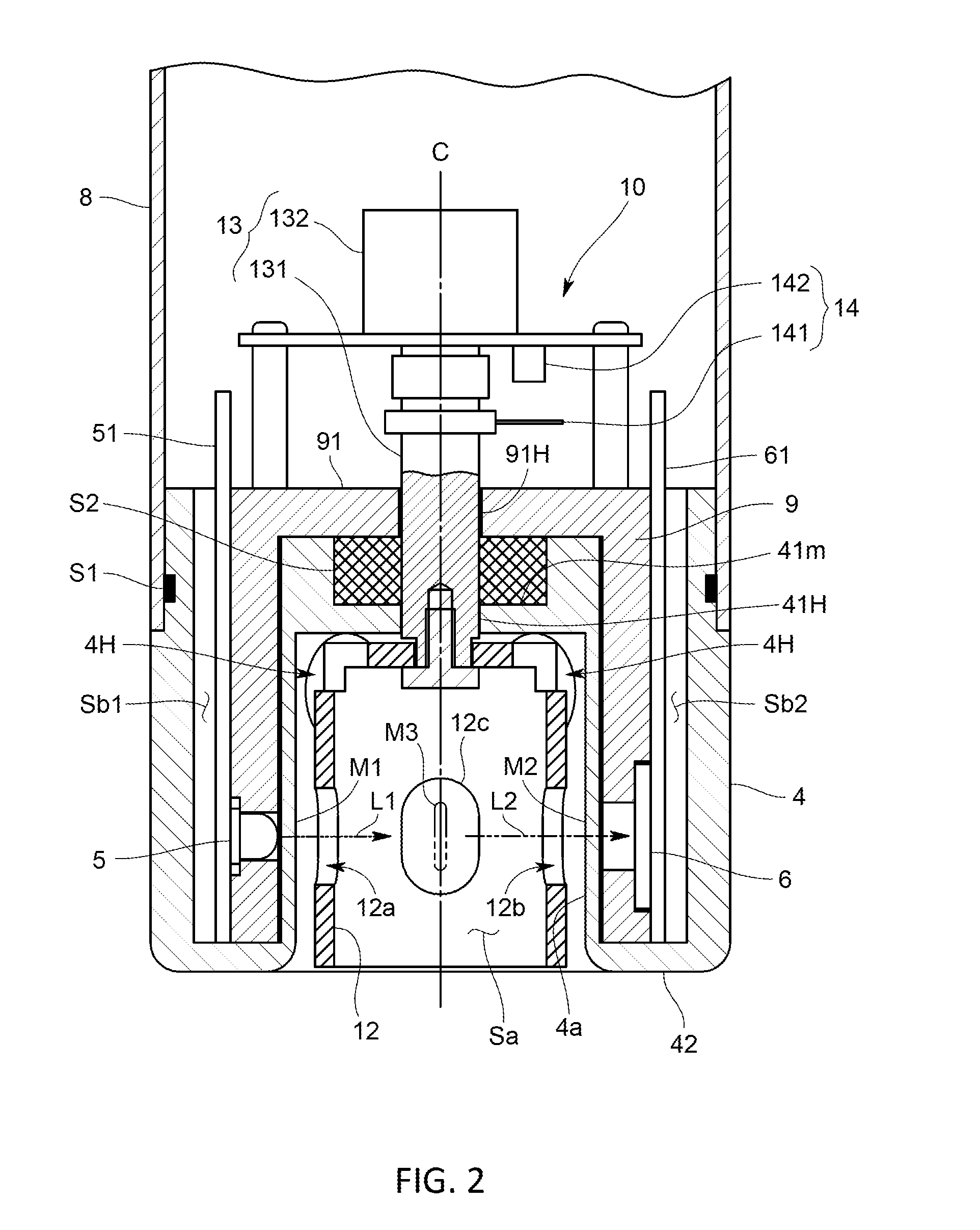
[0082]According to the turbidimeter 100 configured as described above, since the light absorbing portion 15 is provided by embedding the light absorbing members 15a to 15c in the side wall 42 of the sensor head 4, it is possible to absorb light which passes through the inside of the side wall 42 of the sensor head 4 or which becomes reflected light reflected by the inner surface of the side wall 42, and the stray light composed of such light can be prevented from being received by the transmitted light detector 6 and scattered light detector 7 (especially, scattered light detector 7). Thus, accurate measurement can be obtained.

[0083]Note that the present invention should not be limited to the above embodiments.

[0084]For example, in the above embodiments, although the accommodating spaces Sb1 to Sb3 are formed to respectively correspond to the light source 5, transmitted light detector 6, and scattered light detector 7, it may be possible to form accommodat...


PUM

PropertyMeasurementUnit
optical transparencyaaaaaaaaaa
thicknessaaaaaaaaaa
cylindrical shapeaaaaaaaaaa

Abstract

The present invention is intended to provide a turbidimeter having a simple and sturdy structure which is hard to break and exhibits excellent long-term stability by reducing a number of sealing positions, wherein a cylindrical sensor head forming a measurement space is formed of an optically-transparent material. A side wall of the sensor head has accommodating spaces for accommodating a light source, transmitted light detector, and scattered light detector. An inner surface of the side wall of the sensor head is configured to serve as: an optical window for guiding inspection light to the measurement space; an optical window for guiding transmitted light to the transmitted light detector; and an optical window for guiding scattered light to the scattered light detector.

Description

TECHNICAL FIELD[0001]The present invention relates to a turbidimeter for measuring turbidity of a liquid sample.BACKGROUND ART[0002]Among conventional turbidity sensors, there is one which includes: a cylindrical measuring cell for accommodating a liquid sample; a light source; a transmitted light detector and scattered light detector; and a sensor accommodating part for accommodating the light source, transmitted light detector, and scattered light detector, wherein the light source, transmitted light detector, and scattered light detector are provided outside the measuring cell, as disclosed in Patent Literature 1. Both end portions in an axial direction of the measuring cell are fixed to the sensor accommodating part via a sealing member. Then, the light source, transmitted light detector, and scattered light detector are fixed in a space which is formed between the sensor accommodating part and the measuring cell.[0003]Further, the measuring cell includes a first transparent win...

Claims


Application Information

Patent Timeline
Patent Type & Authority Applications(United States)
IPC IPC(8): G01N21/51
CPCG01N21/51G01N21/532
Inventor SUZUKI, RIICHIROKIZAKI, HIROKOMATSUO, AKIKANDA, HIROSHI
Owner HORIBA ADVANCED TECHNO
Why Eureka
Try Eureka