Solar vacuum cup

A vacuum cup and solar energy technology, applied in the field of vacuum cups, can solve the problem of not being able to heat the water in the cup, and achieve the effect of saving energy

Inactive Publication Date: 2008-08-20
宫业兵
View PDF0 Cites 1 Cited by
  • Summary
  • Abstract
  • Description
  • Claims
  • Application Information

AI Technical Summary

Problems solved by technology

[0002] At present, the cups that people usually use are generally thermos cups, also double-layer thermos cups, which have the functions of heat preservation and cold preservation, and cannot heat the water in the cup.

Method used


Image

  • Solar vacuum cup

Examples


Embodiment Construction

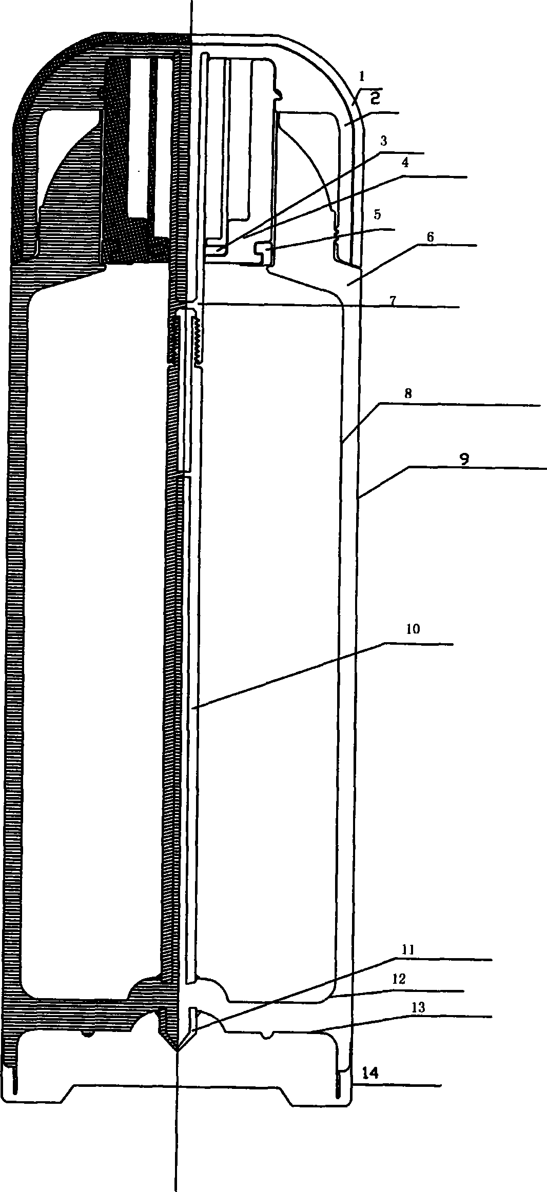
[0009] Such as figure 1 As shown, the present invention is mainly composed of a cup cover and a cup body. A heat-accumulating layer 1 and a vacuum heat-conducting layer 2 are arranged on the cup cover. A heat-conducting meson is arranged in the vacuum heat-conducting layer 2. The vacuum heat-conducting layer 2 is in the middle of the cup cover. There is a cylindrical vacuum column extending toward the cup, and the upper heat-conducting copper tube 7 wraps the cylindrical vacuum column and connects it together. A plastic device 4 connected to the vacuum heat-conducting layer 2 is also provided on the cup cover, and a silicone rubber sealing ring 3 with a sealing effect is provided on the inside of the bottom of the plastic device 4, and a sealing ring 3 is provided on the outside of the bottom of the plastic device 4. Silicone rubber sealing ring5. The stainless steel liner 8 on the cup body and the stainless steel shell 9 form a vacuum layer, to be beneficial to heat preserva...


PUM


Abstract

The invention discloses a solar vacuum cup, comprising a cup lid and a cup body. The invention is characterized in that: a heat-trapped layer 1 and a vacuum heat conduction layer 2 are arranged on the cup lid, and a cylindrical vacuum column extending to the cup body is arranged in the middle of the cup lid on the vacuum heat conduction layer 2, and an upper heat-conduction copper tube 7 enwraps the cylindrical vacuum column to be connected together; a lower heat-conduction copper tube 10 is a cylindrical tube, and the bottom of the lower heat-conduction copper tube 10 penetrates a stainless inner hull bottom 12 and a stainless steel mid bottom 13 to be connected together. The solar vacuum cup has the advantages of making full use of solar energy, being environment-friendly, saving energy sources, providing big convenience to the outdoor foot passengers and obtaining boiled water without any energy source.

Description

technical field [0001] The invention relates to a vacuum cup, specifically a solar vacuum cup which utilizes solar energy to heat water in the cup for a short time. Background technique [0002] At present, the cups that people usually use are generally thermos cups, also double-layer thermos cups, which have the functions of heat preservation and cold preservation, and cannot heat the water in the cup. Contents of the invention [0003] The purpose of the present invention is to provide a solar vacuum cup, which can heat the cold water in the cup to boiling water in a short time without using any other energy sources. [0004] In order to achieve the above object, the present invention is mainly composed of a cup cover and a cup body, and is characterized in that a heat-accumulating layer 1 and a vacuum heat-conducting layer 2 are arranged on the cup cover, and a heat-conducting meson is arranged in the vacuum heat-conducting layer 2, and the vacuum heat-conducting layer ...

Claims


Application Information

Patent Timeline
Patent Type & Authority Applications(China)
IPC IPC(8): A47J41/02A45F3/16A47G19/22F24J2/00F24J2/46F24S10/40F24S10/70
CPCY02E10/44
Inventor 龚辉武宫业兵
Owner 宫业兵
Why Eureka
Try Eureka