Engine tail gas afterheat exchange method

An engine and exhaust gas technology, which is applied in the direction of engine components, combustion engines, machines/engines, etc., can solve problems such as restricting development, large consumption, and heat conduction effects of exhaust gas recovery devices, so as to avoid continuity, uninterruptibility, and low cost Effect

Inactive Publication Date: 2017-04-05
夏树伟
View PDF0 Cites 2 Cited by
  • Summary
  • Abstract
  • Description
  • Claims
  • Application Information

AI Technical Summary

Problems solved by technology

[0002] At present, only 40.5% of the domestic 12V190 series diesel engine works is converted into effective mechanical power, and 59.5% of the heat exchanger (3) includes end panels connected with the smoke chamber (2) and the anechoic chamber (8) respectively (9), the two end panels (9) and the side walls form a closed chamber, and a plurality of heat exchange tubes ( 10) Solve the following technical problems: 1. The flue gas recovery device cannot form resistance to the exhaust of diesel engines
2. The influence of carbon deposits from diesel engine exhaust on the heat conduction of the exhaust gas recovery device
In view of the above problems, the development of this technical field is restricted
However, the drilling team uses boilers to prevent freezing and heat preservation of drilling equipment in winter production. There are two main problems in this heat preservation method: 1. It consumes a lot of energy. According to statistics, a drilling team will burn about 300 tons of coal and consume about 300 tons of coal on average during the winter heating period. 2000 square meters, resulting in a large amount of energy waste and environmental pollution, high operating costs
2. Boiler water vapor is easy to freeze after condensation
At present, the large amount of heat energy in the exhaust gas of diesel engines cannot be well utilized. On the other hand, it needs to consume a large amount of coal and water resources for winter antifreeze and heat preservation of drilling rig equipment. This is a very prominent problem.

Method used


Image

  • Engine tail gas afterheat exchange method

Examples


Embodiment

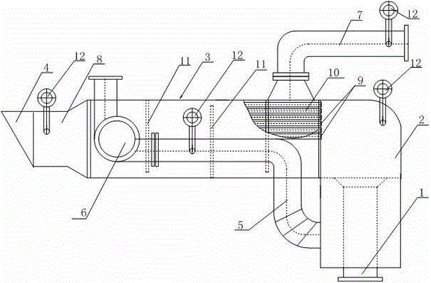
[0018] Such as figure 1 As shown, a method for exchanging waste heat of engine exhaust gas in the present invention includes a flue gas inlet 1, a smoke chamber 2, a heat exchanger 3, an anechoic chamber 8, and a smoke exhaust port 4 connected in sequence, and also includes an air inlet pipe 5, and The fan 6 installed on the air inlet pipe 5, the output end of the fan 6 enters the heat exchanger, and the heat exchanger includes an end panel 9 connected to the smoke chamber 2 and the muffler chamber 8 respectively, and forms an airtight seal with the two end panels 9. On the side wall of the chamber, a plurality of heat exchange tubes 10 connecting the smoke chamber and the muffler chamber are installed between the two end panels 9, and four baffles 11 are installed in the heat exchanger, and the baffles 11 are connected with the heat exchange The end panels 9 of the heat exchanger are parallel, and any two adjacent baffles 11 are connected to the opposite surfaces of the side ...


PUM


Abstract

The invention discloses an engine tail gas afterheat exchange method. The engine tail gas afterheat exchange method comprises a smoke inlet, a smoke chamber, a heat exchanger, a silencing chamber and a smoke discharge port connected in sequence, and further comprises an intake pipe and a fan mounted on the intake pipe; an output end of the fan enters the heat exchanger; an opening is formed in the heat exchanger; and a hot air exhaust pipe is mounted on the opening. After the heat exchange is performed for high-temperature tail gas of an engine, well drilling equipment is heated and insulated by high-temperature hot air to replace use of a boiler; and compared with a water heating mode, the engine tail gas afterheat exchange method not only can achieve a heating effect, but also can start the fan for heat exchange and air supply when needed, so that the water heating continuity is prevented, the cost is far lower than that in water heating, and the purposes of emission reduction and energy conservation are achieved.

Description

technical field [0001] The invention relates to a heat exchange device, in particular to a waste heat exchange method for engine exhaust. Background technique [0002] At present, only 40.5% of the domestic 12V190 series diesel engine works is converted into effective mechanical power, and 59.5% of the heat exchanger (3) includes end panels connected with the smoke chamber (2) and the anechoic chamber (8) respectively (9), the two end panels (9) and the side walls form a closed chamber, and a plurality of heat exchange tubes ( 10) Solve the following technical problems: 1. The flue gas recovery device cannot form resistance to the exhaust of the diesel engine. 2. The influence of carbon deposits from diesel engine exhaust on the heat conduction of the exhaust gas recovery device. 3. Selection of recycling medium. In view of the above problems, the development of this technical field is restricted. However, the drilling team uses boilers to prevent freezing and heat prese...

Claims


Application Information

Patent Timeline
Patent Type & Authority Applications(China)
IPC IPC(8): F02G5/02
CPCY02T10/12
Inventor 夏树伟
Owner 夏树伟
Why Eureka
Try Eureka