Exhaust brake

An exhaust brake and brake technology, applied in the direction of engine control, machine/engine, mechanical equipment, etc., can solve the problems of non-adjustment, brake lag, unstable back pressure, etc., to achieve sensitive response, stable and reliable braking. Effect

Inactive Publication Date: 2008-08-27
李瑞强 +2
View PDF0 Cites 34 Cited by
  • Summary
  • Abstract
  • Description
  • Claims
  • Application Information

AI Technical Summary

Problems solved by technology

[0005] Aiming at the disadvantages of the existing exhaust brakes that the back pressure is not stable and cannot be adjusted, and the brake is severely lagging behind, the purpose of the present invention is to provide a brake that can release excessive pressure in time, keep the brake working pressure stable, and have a sensitive brake response. exhaust brake

Method used


Image

  • Exhaust brake
  • Exhaust brake
  • Exhaust brake

Examples


Embodiment Construction

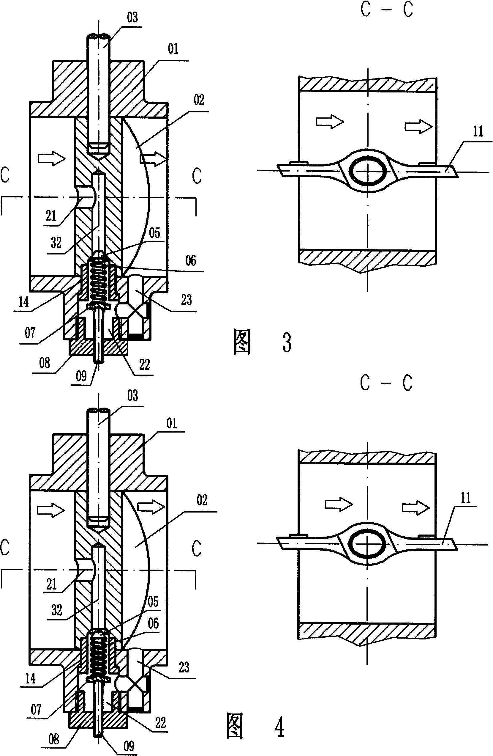
[0024] The specific implementation manner of the present invention will be introduced below with reference to FIG. 3 and FIG. 4 . Figure 3 shows that the exhaust gas channel is in a disconnected state, and Figure 4 shows that the exhaust gas channel is in an open state. All parts with the same function as before in Fig. 3 and Fig. 4 use the same number.

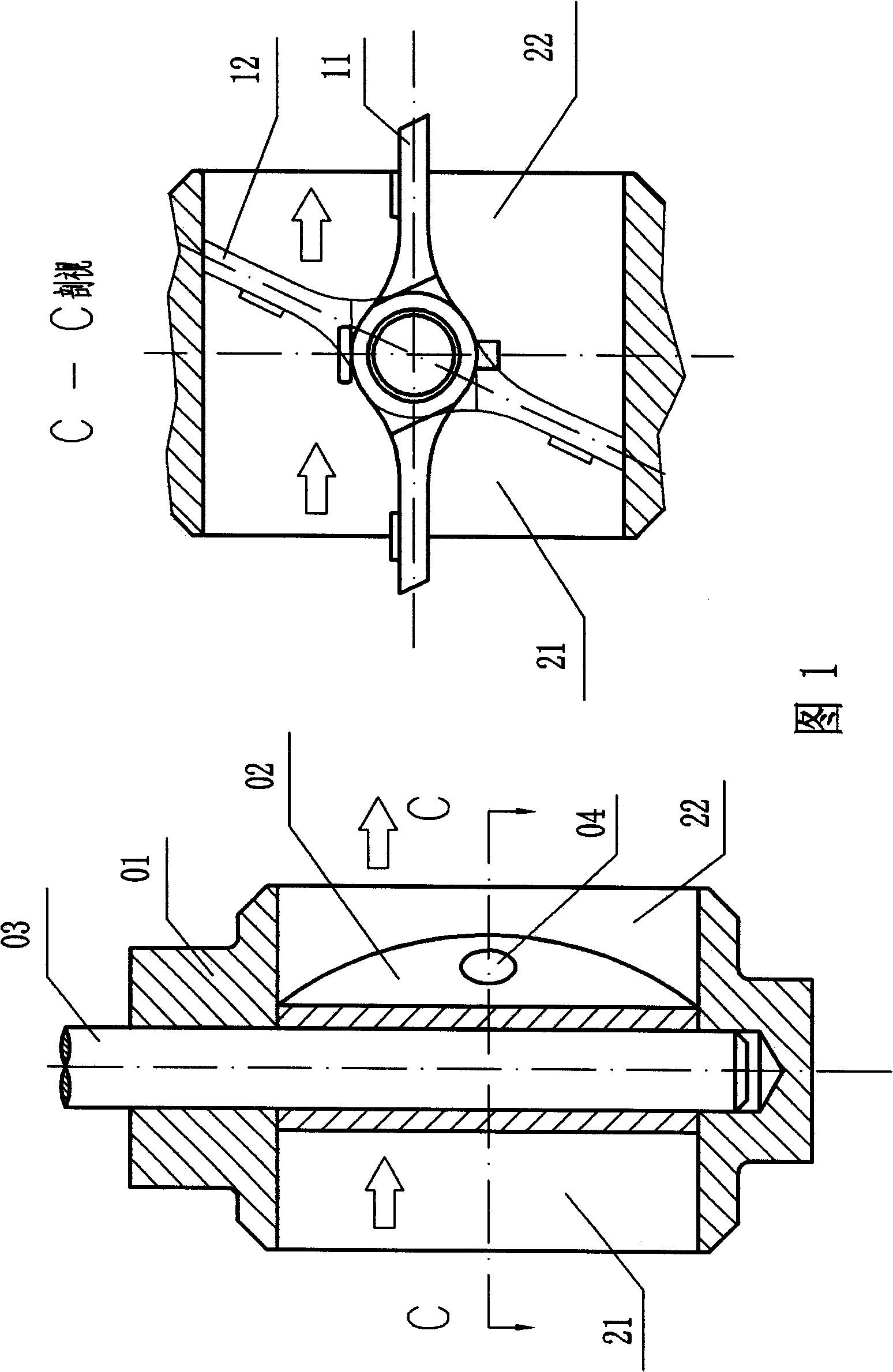
[0025] The valve body 01 is used to assemble the components that complete the braking function into an assembly, the support rod 03 and the support sleeve 14 are used to fix the disc 02 at the designated position of the valve body 01, and the direction of the arrow represents the flow direction of the exhaust gas. There are cavity 21 and cavity 22 on the disc 02, and a pressure reducing valve 05 is pressed on the bottom of cavity 22 by spring 06, pressure plate 07, adjustment support 09 and cover 08. At this time, the pressure reducing valve 05 connects cavity 22 and cavity 32 It is divided into two parts; when no braking is...


PUM


Abstract

The invention relates to an exhaust brake with a decompressor and a method for preventing the formation of the overpressure in the exhaust brake. The operating pressure of the exhaust brake is reliable and adjustable. The exhaust brake comprises a valve body, a disc, a supporting rod, a supporting sleeve, a reducing valve, a spring and an adjustable bolt and does not have a pressure relief vent, wherein, the supporting rod and the supporting sleeve are used for fixing the disc, the reducing valve is used for stably activating the exhaust resistance, the spring is used for adjusting the size of the operating back pressure of an assembly. The exhaust brake with the decompressor can release the excess pressure in time when the pressure surpasses the presetting value due to any unforeseen circumstances and guarantees the stable and reliable operating pressure; moreover, the exhaust brake with the decompressor has adjustable operating pressure, simple and convenient implementation and reliable performance.

Description

technical field [0001] The invention relates to an exhaust brake with a decompression device and to a method for preventing the build-up of an overpressure in the exhaust brake. Make the working pressure of the exhaust brake stable, reliable and adjustable. technical background [0002] Automobile braking system is one of the important devices for high-speed and safe driving of modern automobiles. When the vehicle needs to decelerate, especially in mountainous areas or when urban buses need to brake frequently, if the service brake is used frequently, the wheel brake will overheat and the braking performance will decline. If emergency measures (stop cooling) are not taken in time, even This can result in complete failure of the brakes and a dangerous vehicle situation. Therefore, it is very necessary to adopt non-fading auxiliary braking system for such situations. The use of auxiliary braking devices can enhance the braking performance of the vehicle, and the vehicle can...

Claims


Application Information

Patent Timeline
Patent Type & Authority Applications(China)
IPC IPC(8): F02D9/06
Inventor 李瑞强林华郭烨
Owner 李瑞强
Why Eureka
Try Eureka