Shrinking connecting-rod locking mechanism

A technology of telescopic connecting rod and locking mechanism, which is applied in the direction of mechanical equipment, fixing devices, electrical components, etc., to achieve the effect of reliable locking, good rigidity, and improved impact resistance

Inactive Publication Date: 2008-08-27
HARBIN INST OF TECH +1
View PDF0 Cites 10 Cited by
  • Summary
  • Abstract
  • Description
  • Claims
  • Application Information

AI Technical Summary

Problems solved by technology

[0003] The purpose of the present invention is to provide a telescopic link locking mechanism, which can solve the problem of using the limited space between the extension arm and the loading cylinder and the relative movement of the two to realize reliable and accurate locking of the extension arm in the loading cylinder after it is fully expanded. positioning problem

Method used


Image

  • Shrinking connecting-rod locking mechanism
  • Shrinking connecting-rod locking mechanism
  • Shrinking connecting-rod locking mechanism

Examples


specific Embodiment approach 1

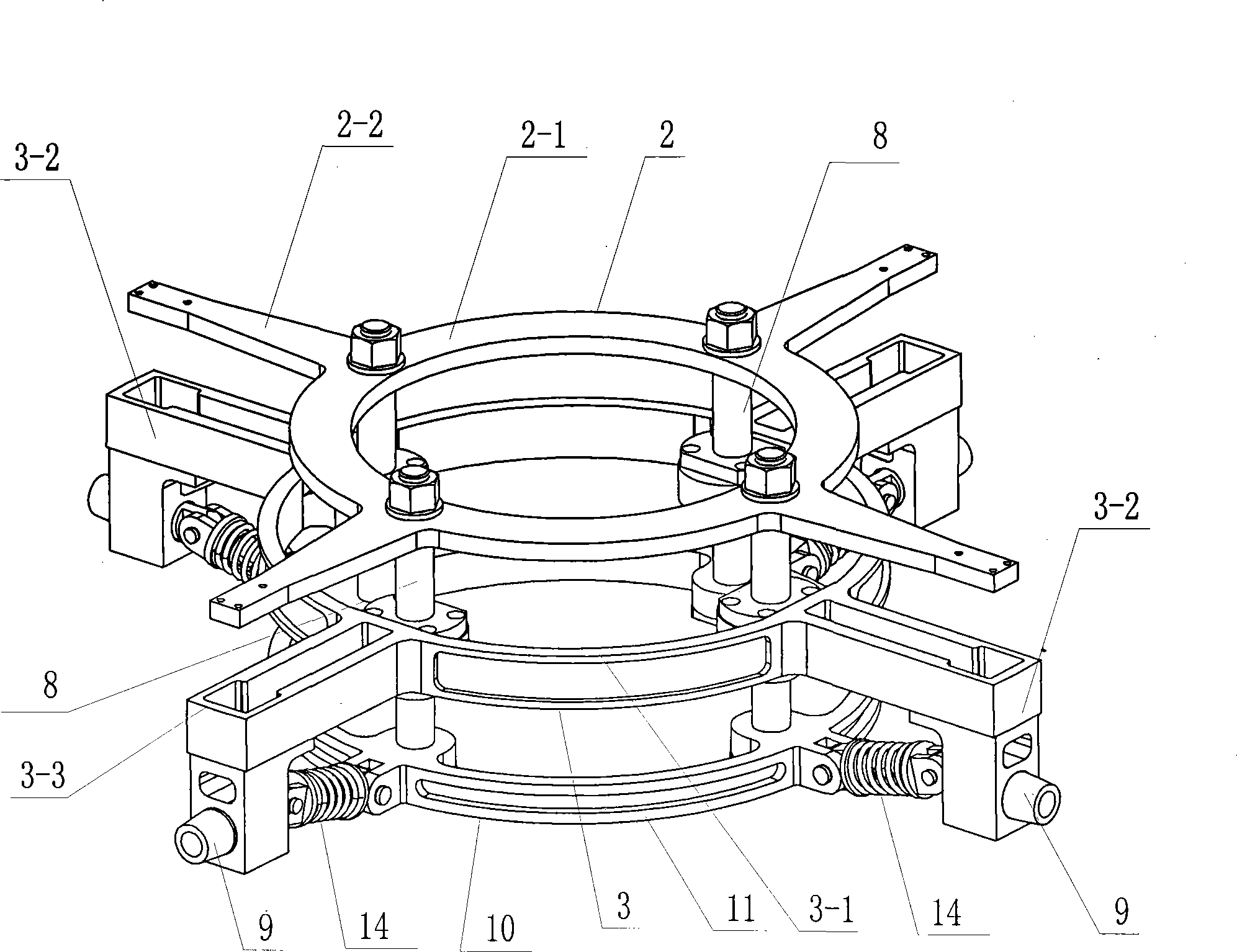
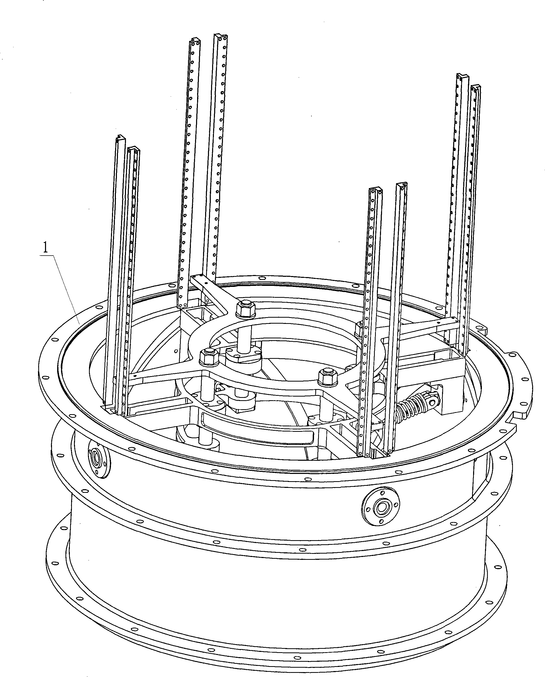
[0007] Specific implementation mode one: combine Figure 1~5 To illustrate this embodiment, the telescopic link locking mechanism described in this embodiment is composed of a driving member 2, a positioning member 3, four linear slide rails 8, and a connecting rod structure assembly 10. The driving member 2 and the positioning member 3 are The last unit of the extension arm is made into a double-layer structure. The connecting rod structure assembly 10 is composed of four locking blocks 9, four telescopic connecting rods 14, and connecting parts 11. The driving part 2, the positioning part 3 and the connecting parts The parts 11 are arranged in parallel in the loading cylinder 1 in sequence along the axial direction. The driving part 2 and the connecting part 11 of the positioning part 3 are connected together by four linear slide rails 8. The four cantilever arms 3-2 on the positioning part 3 Connect with four locking blocks 9 respectively, and the four locking blocks 9 are ...

specific Embodiment approach 2

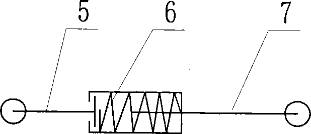
[0008] Specific implementation mode two: combination figure 1 , figure 2 with Figure 5 Describe this embodiment, the four telescopic links 14 described in this embodiment are all made up of outer end link 5, spring 6, inner end link 7, and one end of said outer end link 5 is connected to the inner end by spring 6. One end of the connecting rod 7 is connected; the other ends of the four outer connecting rods 5 are respectively hinged with the four lock blocks 9 , and the other ends of the four inner connecting rods 7 are respectively hinged with the connecting piece 11 . The spring 6 can eliminate the gap between the mechanisms, and make the mechanism have force closure characteristics. Other components and connections are the same as those in the first embodiment.

specific Embodiment approach 3

[0009] Specific implementation mode three: combination figure 1 , figure 2 To illustrate this embodiment, the driver 2 described in this embodiment is composed of a driver ring 2-1 and four driver cantilever arms 2-2, and the four driver cantilever arms 2-2 are evenly distributed on the driver ring 2-1 on the circumference of the outer circle and affixed to the outer surface of the driver ring 2-1. Such design can make the locking of the mechanism firm and stable. Other components and connections are the same as those in the first embodiment.


PUM


Abstract

A telescopic connecting rod locking mechanism relates to a locking mechanism. The invention solves the problem of realizing the reliable and accurate locking location of a fully unfolded extending arm inside a loading drum by means of a limited space positioned between the extending arm and the loading drum and the relative motion of both the extending arm and the loading drum. The invention adopts the following structure: a drive piece (2), a locating piece (3) and a connecting piece (11) are connected together through four linear slide rails (8); four cantilevers (3-2) arranged on the locating piece (3) are respectively connected with four locking pieces (9) which are respectively articulated with one end of each of four telescopic connecting rods (14); the other end of each of the four telescopic connecting rods (14) is articulated with the connecting piece (11); the internal wall of a loading drum (1) which is arranged between the drive piece (2) and the locating piece (3) is provided with a retaining platform (12); moreover, the internal wall of the loading drum (1) is provided with a location hole (13). The telescopic connecting rod locking mechanism, which makes use of the limited space positioned between an extending arm and a loading drum, realizes the locking location and unlocking of the extending arm and the loading drum.

Description

technical field [0001] The invention relates to a locking mechanism, in particular to a locking mechanism between a large-scale space extension arm and its loading cylinder after it is fully deployed. Background technique [0002] The problem of accurate locking in the loading tube of the large-scale space extension arm after it is fully expanded needs to be solved urgently. Because the loading barrel is a cylindrical structure, there is not enough space between the extension arm and the loading barrel to place the traditional locking device and its locking drive power source, so consider using the limited space between the extension arm and the loading barrel and its two The relative movement of the arm is used to solve the problem of reliable and accurate locking and positioning in the loading cylinder after the extension arm is fully deployed. Contents of the invention [0003] The purpose of the present invention is to provide a telescopic link locking mechanism, whic...

Claims


Application Information

Patent Timeline
Patent Type & Authority Applications(China)
IPC IPC(8): F16B1/00H01Q3/01
Inventor 邓宗全罗阿妮刘荣强郭宏伟
Owner HARBIN INST OF TECH
Why Eureka
Try Eureka