Wireless circuit device
A radio and receiving circuit technology, which is applied in the field of wireless circuit devices, can solve the problems of deterioration of receiving signal reception sensitivity, inability to achieve low current consumption of the receiving circuit, etc., and achieve the effect of realizing low power consumption and low power consumption
- Summary
- Abstract
- Description
- Claims
- Application Information
AI Technical Summary
Problems solved by technology
Method used
Image

Examples
no. 1 Embodiment approach
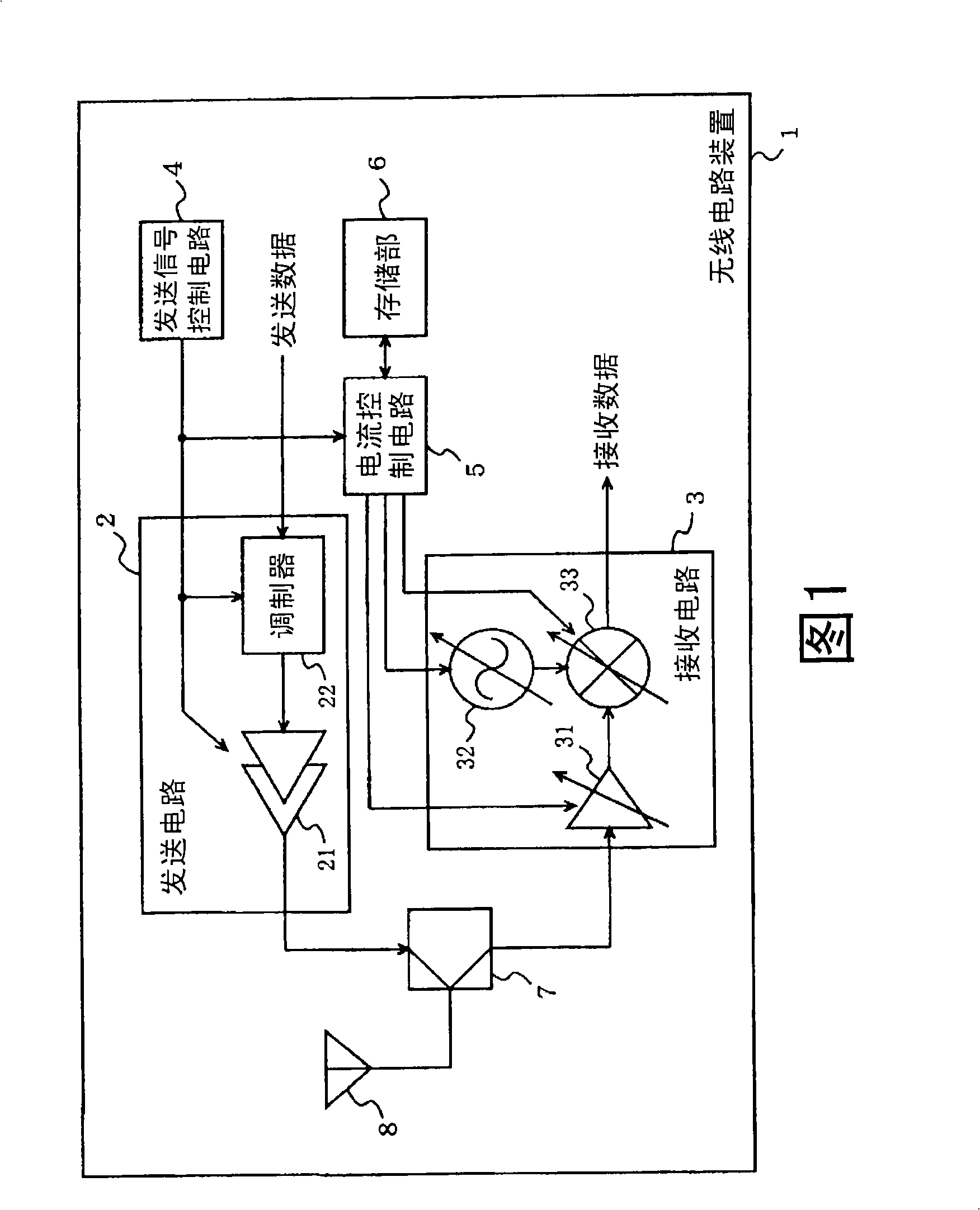
[0082]FIG. 1 is a block diagram showing a functional configuration of a wireless circuit device 1 of the present invention. In FIG. 1 , a wireless circuit device 1 includes a transmission circuit 2 , a reception circuit 3 , a transmission signal control circuit 4 , a current control circuit 5 , a storage unit 6 , an antenna duplexer 7 , and an antenna 8 . The transmission circuit 2 includes a power amplifier 21 and a modulator 22 . The receiving circuit 3 includes a low noise amplifier 31 , a local signal oscillator 32 and a mixer 33 .
[0083] Modulator 22 modulates transmission data. The modulation method used in the modulator 22 is specified by the transmission signal control circuit 4 .
[0084] The power amplifier 21 amplifies the power of the signal modulated by the modulator 22 and outputs it as a transmission signal. The amplification ratio of the power amplifier 21 is specified by the transmission signal control circuit 4 .
[0085] The transmission signal control...
no. 2 Embodiment approach
[0101] FIG. 4 is a block diagram showing a functional configuration of a radio circuit device 1a according to a second embodiment of the present invention. In FIG. 4 , blocks having the same functions as those of the radio circuit device 1 according to the first embodiment are denoted by the same reference numerals, and description thereof will be omitted. In the wireless circuit device 1a, the difference from the wireless circuit device 1 is that the current control circuit 5 is replaced by the current control circuit 5a, the storage unit 6 is replaced by the storage unit 6a, the receiving circuit 3 is replaced by the receiving circuit 3a, and the receiving circuit 3 is replaced by the receiving circuit 3a. The circuit 3a includes a baseband circuit (BB circuit) 34, and a receiving level detection circuit 9 is added.
[0102] The storage unit 6a stores control information corresponding to the frequency of the transmission signal, the power of the transmission signal, and the ...
no. 3 Embodiment approach
[0111] FIG. 6 is a block diagram showing a functional configuration of a wireless circuit device 1b according to a third embodiment of the present invention. In FIG. 6 , blocks having the same functions as those of the radio circuit device 1 or 1a according to the first or second embodiment are denoted by the same reference numerals, and description thereof will be omitted. In the wireless circuit device 1b, the difference from the wireless circuit device 1 is that the current control circuit 5 is replaced with a current control circuit 5b, the storage unit 6 is replaced with a storage unit 6b, and the receiving circuit 3 is replaced with a receiving circuit 3a. The circuit 3a includes a baseband circuit (BB circuit) 34, a reception level detection circuit 9 is added, and a filter 10 and a reception level detection circuit 11 near the desired wave are added.
[0112] The storage unit 6b is related to the frequency of the transmission signal, the power of the transmission signa...
PUM
 Abstract
Description
Claims
Application Information
 - Generate Ideas
- Intellectual Property
- Life Sciences
- Materials
- Tech Scout
- Unparalleled Data Quality
- Higher Quality Content
- 60% Fewer Hallucinations
Browse by: Latest US Patents, China's latest patents, Technical Efficacy Thesaurus, Application Domain, Technology Topic, Popular Technical Reports.
© 2025 PatSnap. All rights reserved.Legal|Privacy policy|Modern Slavery Act Transparency Statement|Sitemap|About US| Contact US: help@patsnap.com