Eureka AIR delivers breakthrough ideas for toughest innovation challenges, trusted by R&D personnel around the world.

Prefabricated element for floor

A technology for prefabricated components and floor slabs, applied in the field of prefabricated components for floor slabs, can solve the problems of easy breakage, partial solidity, and low overall density of the formwork.

Inactive Publication Date: 2008-09-10
湖南邱则有专利战略策划有限公司
View PDF0 Cites 8 Cited by
  • Summary
  • Abstract
  • Description
  • Claims
  • Application Information

AI Technical Summary

Problems solved by technology

[0002] At present, in the formwork technology used in China, bamboo, wood, steel formwork or prefabricated panels are generally used as formwork. Prefabricated panels are generally produced manually or manually and mechanically vibrated. The overall density of the formwork manufactured in this way is low and the strength is low. , is easy to be damaged during the construction process, and in the hollow hole-forming technology of cast-in-place concrete, components such as pre-embedded hollow shells, boxes or pipes are generally used to evacuate the cast-in-place concrete to form holes, while the existing hollow shells, boxes or pipes Components such as body are generally produced manually or semi-mechanized by external mold method or internal mold method. Although the components produced in this way can be used to form hollow holes in cast-in-place concrete floor slabs, their walls have low density and low strength. , it is very easy to be damaged during construction and application, resulting in partial solidity and affecting the structure. At the same time, the surface of the product is too smooth, it is not easy to bond with cast-in-place concrete, and it is easy to form a joint interface, especially when it is applied to the floor. The use of vibrating equipment is easy to damage the wall and form a partial solid slab, which affects the overall performance of the floor. Therefore, it is urgent to develop a prefabricated component for the floor.

Method used


Image

  • Prefabricated element for floor
  • Prefabricated element for floor
  • Prefabricated element for floor

Examples


Embodiment Construction

[0075] The present invention will be further described below in conjunction with the accompanying drawings and embodiments.

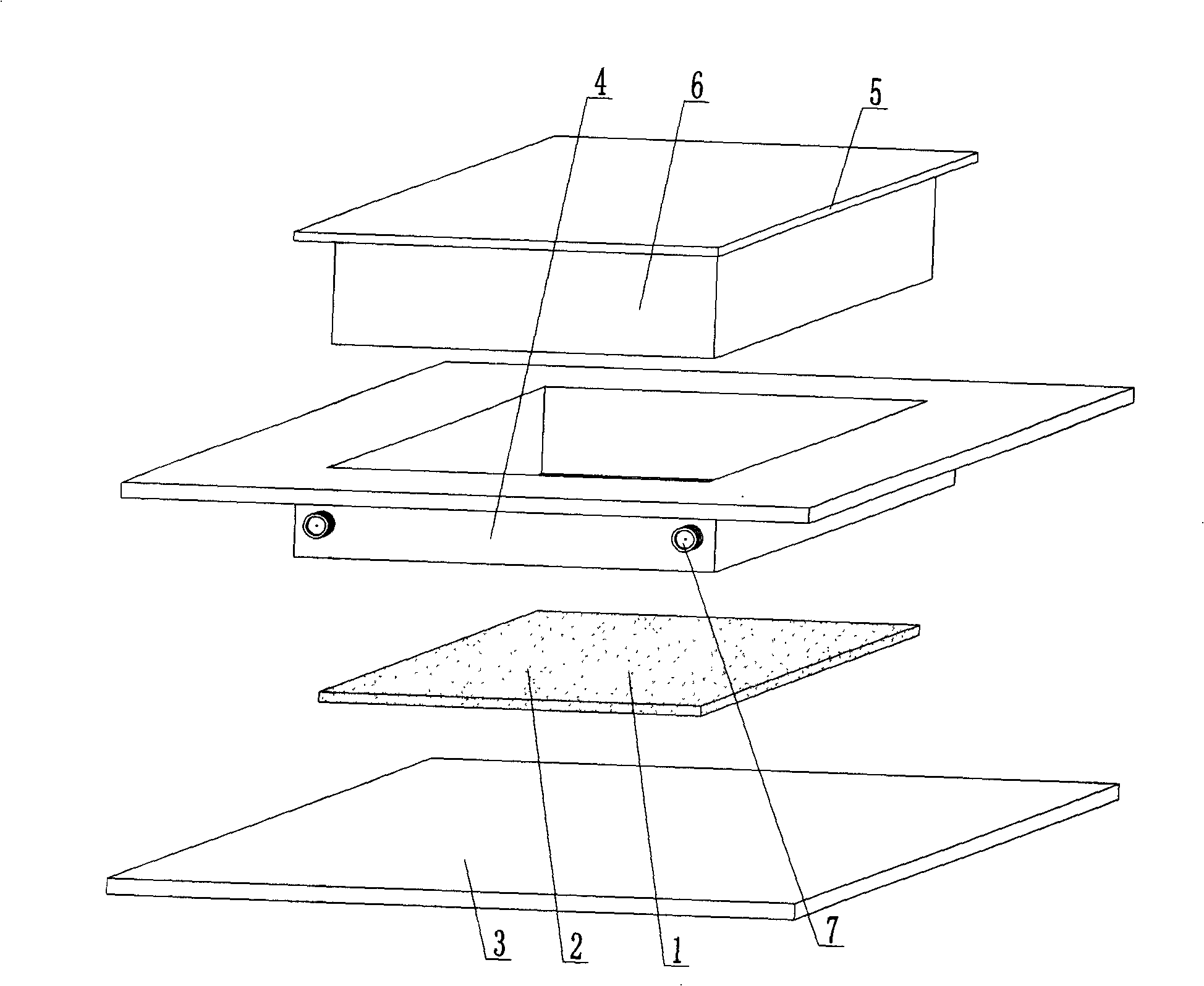
[0076] As shown in the accompanying drawings, the present invention includes a prefabricated reinforced concrete panel 1, which is characterized in that the prefabricated reinforced concrete panel 1 is a reinforced concrete material 2 arranged on the bottom formwork 3 and in the side formwork frame 4, and the reinforced concrete material has an upper vertical movement plus The upper pressing plate 5 is pressed, the upper pressing plate 5 is provided with an indenter 6, the bottom formwork 3 or / and the upper indenter 6 or / and the side formwork is provided with a vibrator 7, and the prefabricated reinforced concrete panel 1 is compressed and pressed by the upper indenter 6 Type or vibrating pressure head 6 compression molding, bottom formwork 3 vibrates at the same time and forms, constitutes the plate member of lower formwork, upper pressure head 6 upper ...


PUM

PropertyMeasurementUnit
Thicknessaaaaaaaaaa
Lengthaaaaaaaaaa

Abstract

The invention relates to a prefabricated component for floor slabs, comprising a prefabricated concrete plate (1). The prefabricated component is characterized in that: in the prefabricated concrete plate (1), bar reinforced concrete materials (2) are arranged on a bottom molding board (3) and inside a side mold frame (4); an upper press plate (5) which moves in the vertical direction to pressurize is arranged above the bar reinforced concrete materials (2); a pressure head (6) is arranged under the upper press plate (5); a vibrator (7) is arranged on the bottom molding board (3) or / and the upper pressure head (6) or / and the side mold frame; the prefabricated concrete plate (1) is formed by pressing of upper pressure head (6) compression or vibrating pressure head (6) compression and simultaneously by vibration of the bottom molding board (3), thereby forming a plate-shaped component formed by pressurizing and vibrating an upper splint and a lower splint of a lower mold board and the upper pressure head (6). The prefabricated component can be applied to various constructions such as cast-in-place slab floors, roofs, walls, foundation mats and road and bridge works, and is especially suitable for hollow flat slabs.

Description

(1) Technical field [0001] The invention relates to a prefabricated component for floor slabs. (2) Background technology [0002] At present, in the formwork technology used in China, bamboo, wood, steel formwork or prefabricated panels are generally used as formwork. Prefabricated panels are generally produced manually or manually and mechanically vibrated. The overall density of the formwork manufactured in this way is low and the strength is low. , is easy to be damaged during the construction process, and in the hollow hole-forming technology of cast-in-place concrete, components such as pre-embedded hollow shells, boxes or pipes are generally used to evacuate the cast-in-place concrete to form holes, while the existing hollow shells, boxes or pipes Components such as body are generally produced manually or semi-mechanized by external mold method or internal mold method. Although the components produced in this way can be used to form hollow holes in cast-in-place concre...

Claims


Application Information

Patent Timeline
IPC IPC(8): E04C1/00B28B3/00B28B3/02B28B1/08E04C2/30E04B5/16E04B5/36
Inventor 邱则有
Owner 湖南邱则有专利战略策划有限公司
Why Eureka
Eureka Blog
Learn More