Post-filter for microphone array

A post-filter and microphone array technology, which is applied in the direction of instruments, sensors, transducer circuits, etc., can solve problems such as performance degradation

Inactive Publication Date: 2008-09-10
TOYOTA JIDOSHA KK
View PDF0 Cites 33 Cited by
  • Summary
  • Abstract
  • Description
  • Claims
  • Application Information

AI Technical Summary

Problems solved by technology

[0045] The McCowan post-filter is premised on the use of multi-channel recordings in offices, and was proposed to achieve improved performance in this environment compared to the Zelinski post-filter, however, if the pre-assumed coherence function There is a difference between the actual coherence function and the performance will be degraded

Method used


Image

  • Post-filter for microphone array
  • Post-filter for microphone array
  • Post-filter for microphone array

Examples


Embodiment Construction

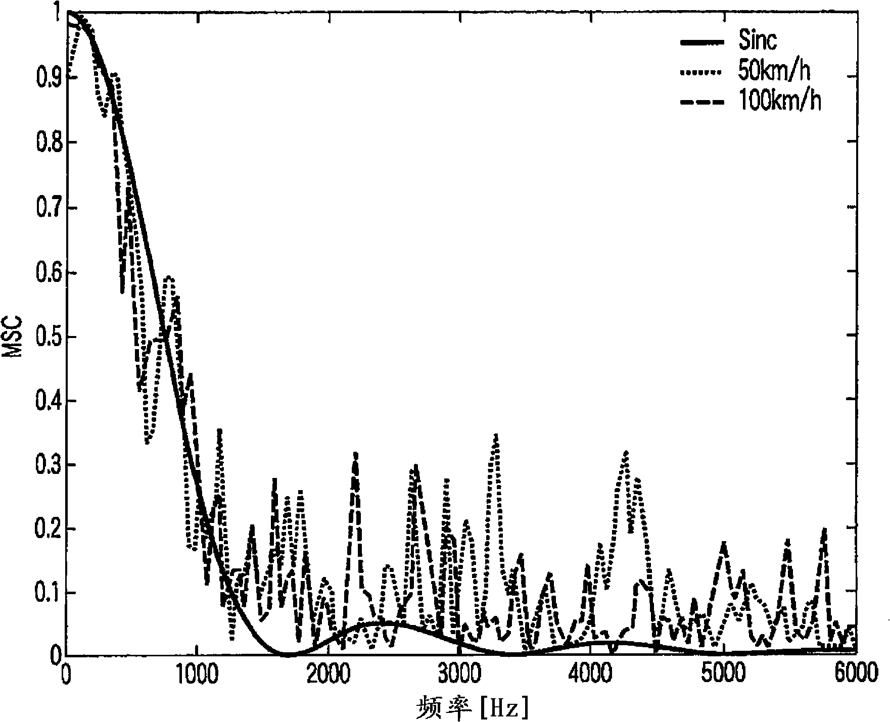
[0068] [21] Embodiments of the present invention will be described with reference to the drawings. In the following description, first, the coherence function in the model noise field and its application will be described. Next, a hybrid postfilter in a diffuse noise field will be described, and finally, advantages of the postfilter according to the present invention will be described.

[0069] [22] To characterize the noise field, the complex coherence function defined by

[0070] [Formula 5]

[0071] Γ x i x j ( k , l ) = φ x i x j ( k ...


PUM


Abstract

A post-filter includes a microphone array including at least two microphones to which a voice signal are input, a beam former which forms the voice signal input from the microphone array, a divider which divides a target sound containing noise input from the microphone array into at least two frequency bands at a predetermined frequency, a first filter which estimates the filter gain with the noise non-correlated between the microphones, a second filter which estimates a filter gain of one microphone of the microphone array or an average signal of the microphone array, an adder which adds the outputs from the first and second filters to each other, and a unit for reducing the noise based on the outputs from the adder and the beam former.

Description

technical field [0001] The present invention relates to post filters for microphone arrays. Background technique [0002] For convenience and flexibility, it is desirable to have hands-free technology for a variety of applications such as mobile phones and automatic speech recognition systems. As one of the important problems in this technique, there is a problem that the reliability of a signal received by a microphone at a distant place is significantly lowered due to various noises. As a solution to this problem, spatial filtering is conceivable, which uses a microphone array to suppress noise signals from directions other than a predetermined direction. The microphone array brings high-quality speech effects, and has the outstanding advantage of reducing noise. [0003] Recently, there are proposals as follows (refer to Document 1: J. Bitzer, K.U. Simmer and K.-D. Kammeyer, "Multi-Microphone Noise Reduction Techniques as Front-end Devices for Speech Recognition," Speec...

Claims


Application Information

Patent Timeline
Patent Type & Authority Applications(China)
IPC IPC(8): H04R3/00G10L15/20G10L21/02H04R1/40G10L21/0208G10L21/0232G10L21/0264
CPCG10L21/0208G10L2021/02166H04R3/005
Inventor 赤木正人李军峰上地正昭佐佐木和也
Owner TOYOTA JIDOSHA KK
Why Eureka
Try Eureka