Concentricity detection device and its method

A technology for testing equipment and concentricity, applied to measuring devices, installation, optics, etc., can solve problems such as slow speed, error, low efficiency and precision, and achieve the effects of reducing production costs, improving efficiency, and precise control

Inactive Publication Date: 2008-09-17
HONG FU JIN PRECISION IND (SHENZHEN) CO LTD +1
View PDF0 Cites 19 Cited by
  • Summary
  • Abstract
  • Description
  • Claims
  • Application Information

AI Technical Summary

Problems solved by technology

[0004] However, the method of manually rotating the lens barrel is usually slow, low in efficiency and precision, and due to the influence of human fatigue and mood, it is impossible to guarantee that each manual rotation can reach the required angle, and sometimes large error

Method used


Image

  • Concentricity detection device and its method
  • Concentricity detection device and its method
  • Concentricity detection device and its method

Examples


Embodiment Construction

[0016] The present invention will be further described in detail below in conjunction with the accompanying drawings.

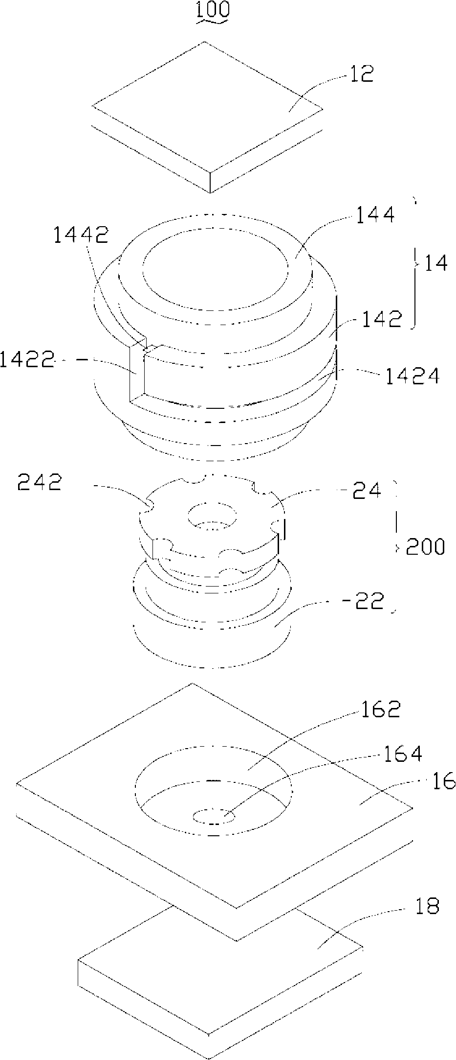
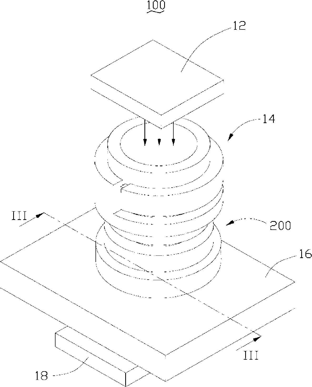
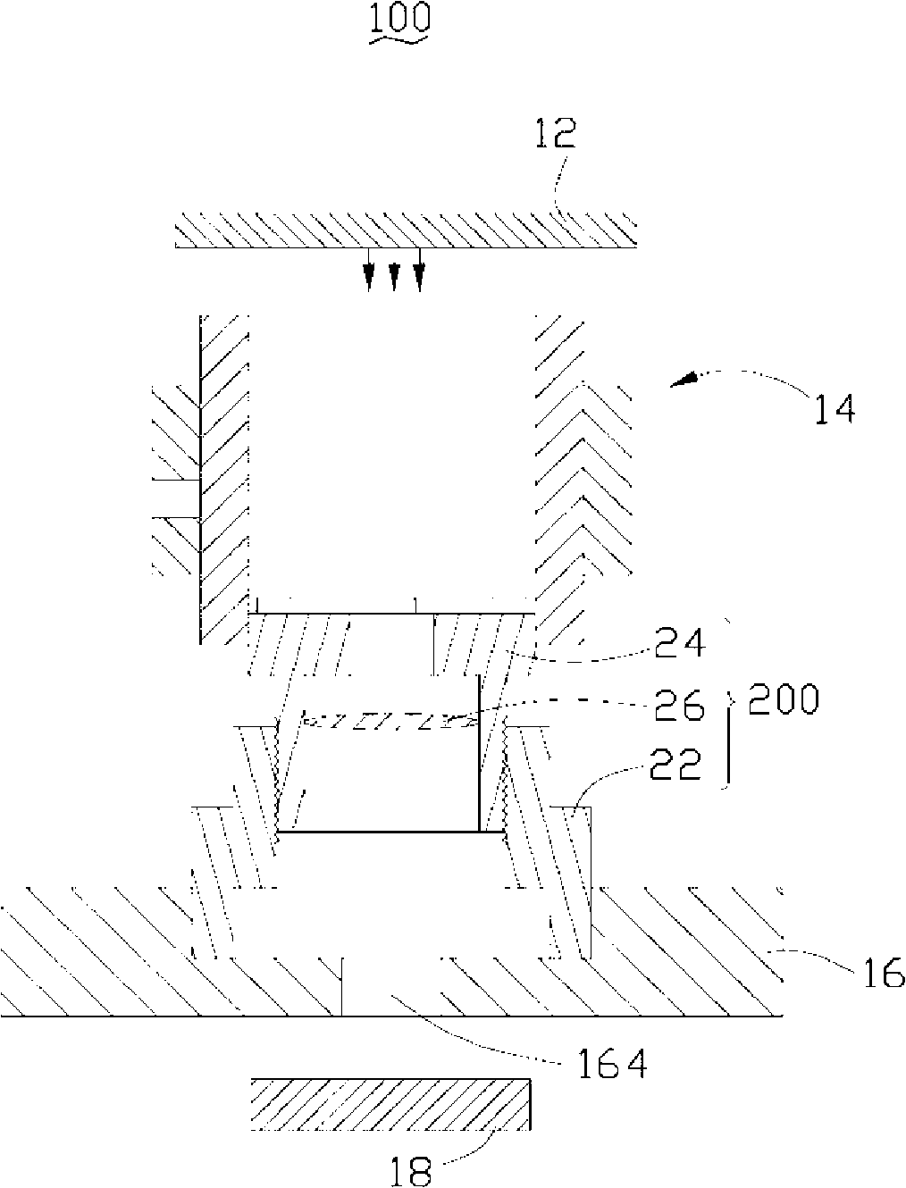
[0017] Please refer to Figure 1 to Figure 3 , is a schematic diagram of the concentricity testing device 100 and the lens module 200 to be tested according to the first embodiment of the present invention.

[0018] The lens module 200 to be tested includes a lens base 22 , a lens barrel 24 disposed in the lens mount 22 and engaged with the lens mount 22 , and at least one lens 26 disposed in the lens barrel. The concentricity detection device 100 is used to detect the axial concentricity between the lens barrel 24 and the lens base 22 after the lens barrel 24 is assembled into the lens base 22, that is, the axis of the lens barrel 24 and the lens base 22. Positional deviation between axes. The outer edge of one end of the lens barrel 24 is provided with a plurality of notches 242 , and the plurality of notches 242 are uniformly arranged on the outer edge o...


PUM


Abstract

The invention relates to a concentricity detection device, which is used for detecting axis concentricity between a lens cone and a microscope stand in a lens mould train. The concentricity detection device includes a light source, a detection rule and a device for detecting an optic axis shift excursion which is opposite to the light resource and is used for recording a projection position of a lens axis and sensing an axis projection shift excursion. The detection rule includes an outer sleeve and an inner sleeve which is arranged inside the outer sleeve; the inner sleeve can be turned at a predetermined angle relative to the outer sleeve and is used for acting in concert with the lens. Furthermore, the invention relates to a concentricity detection method by using the concentricity detection device.

Description

technical field [0001] The invention relates to a concentricity detection device and a detection method, in particular to a lens module concentricity detection device and a detection method thereof. Background technique [0002] In recent years, with the development of optical products, the scope of application of lens modules continues to expand, such as digital cameras, mobile phones with camera functions and other electronic products. For electronic products, especially consumer electronic products, the development trend is light weight and thinner, and the corresponding lens modules are getting smaller and smaller, and the precision requirements are getting higher and higher, so the lens The module assembly process also requires higher precision and stability to ensure production efficiency and yield. [0003] Generally, the assembly steps of the lens module include assembling optical elements such as optical lenses, spacers, and diaphragms into the lens barrel, and the...

Claims


Application Information

Patent Timeline
Patent Type & Authority Applications(China)
IPC IPC(8): G01B11/27
CPCG01B11/272G02B7/02G02B13/001G02B27/62
Inventor 颜士杰
Owner HONG FU JIN PRECISION IND (SHENZHEN) CO LTD
Why Eureka
Try Eureka