Bill processor
A banknote processing device and technology for banknotes are applied to devices for accepting coins, thin material handling, handling coins or valuable banknotes, etc., which can solve the problems of shortening the life of the impeller and achieve the effect of increasing the use time.
- Summary
- Abstract
- Description
- Claims
- Application Information
AI Technical Summary
Problems solved by technology
Method used
Image
Examples
Embodiment 1
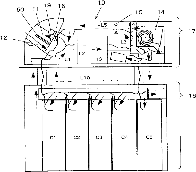
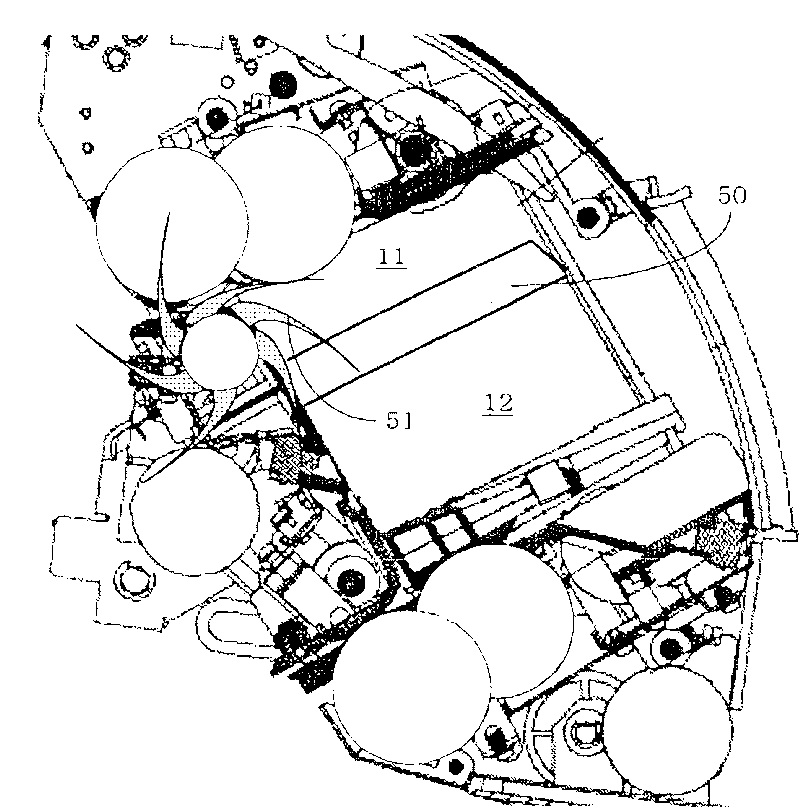
[0032] figure 1 It is a block diagram showing the internal structure of the banknote depositing and dispensing machine 10 as a banknote handling device from the side, figure 2 It is a cross-sectional view showing the structure of the coin outlet 11 as a stacking part from the side. This banknote depositing and withdrawing machine 10 executes depositing and withdrawing processing of banknotes.
[0033] The banknote deposit and withdrawal machine 10 is provided with: a currency outlet 11, which transports the banknotes of the currency or the banknotes rejected when entering the currency; the impeller rotating motor 19, conveys the banknotes to the currency outlet 11; inserted banknotes.
[0034] Such as figure 2 As shown, a coin outlet 11 and a coin inlet 12 are arranged in this order up and down, and a pressing plate 50 is provided to separate the coin outlet 11 and the coin inlet 12 . The pressing plate 50 is moved vertically by a pulse motor (not shown) in accordance wi...
Embodiment 2
[0089] Next, as a second embodiment, a case will be described in which, instead of controlling the start and stop of the rotation of the impeller 51 , the ascending and descending of the pressing plate 50 is controlled.
[0090] Figure 14 It is a flowchart executed by the banknote deposit and withdrawal machine 10 according to the detection of the banknote detection sensor 15 towards the banknote outlet, Figure 15 It is a flow chart executed by the banknote depositing and dispensing machine 10 according to the detection of the coin outlet entrance sensor 16, Figure 16 It is a flow chart of the actions performed by the banknote depositing and dispensing machine 10 when the time is up, Figure 17 It is a cross-sectional view showing the structure of the coin outlet 11 from the side.
[0091] First, before the coin-in transaction, the control unit 31 lowers the pressing plate 50 of the coin outlet 11 to a retracted position where the impeller of the impeller motor 19 does no...
Embodiment 3
[0104] In the third embodiment, in the banknote depositing and dispensing machine 10 configured as described above, in the first embodiment, when the number of motor stops exceeds a predetermined value, the control is shifted to the second embodiment. At this time, when the number of motor stops exceeds the specified value, execute Figure 14 , 15 , 16 of the processing flow can be. Accordingly, the life of the blades of the impeller 51 can be prolonged, and noise can be suppressed to a minimum.
[0105] The present invention is not limited to the configurations of the above-described embodiments, and various embodiments can be obtained.
PUM
 Abstract
Description
Claims
Application Information
 - R&D
- Intellectual Property
- Life Sciences
- Materials
- Tech Scout
- Unparalleled Data Quality
- Higher Quality Content
- 60% Fewer Hallucinations
Browse by: Latest US Patents, China's latest patents, Technical Efficacy Thesaurus, Application Domain, Technology Topic, Popular Technical Reports.
© 2025 PatSnap. All rights reserved.Legal|Privacy policy|Modern Slavery Act Transparency Statement|Sitemap|About US| Contact US: help@patsnap.com


