
Spanner base structure

A technology of wrench and wrench lever, which is applied in the direction of wrench, wrench, screwdriver, etc. It can solve the problems of easy accidental drop, wear material, loss of friction positioning, etc., and achieve the effects of avoiding wear, effectively positioning tools, and reducing costs

Inactive Publication Date: 2008-09-24
邱俞儒
View PDF0 Cites 1 Cited by
  • Summary
  • Abstract
  • Description
  • Claims
  • Application Information

AI Technical Summary

Problems solved by technology

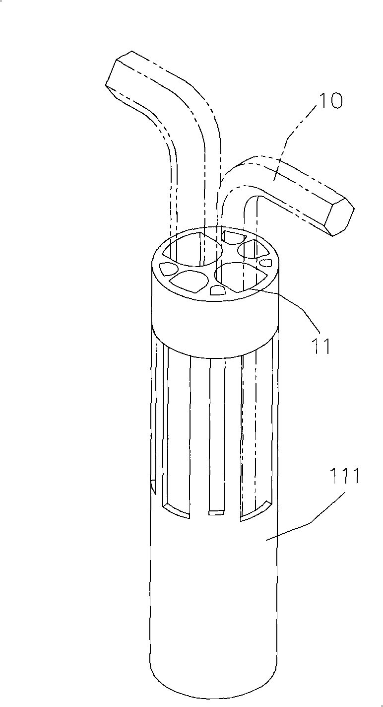
[0004] Since the through hole 111 of the positioning seat 11 is not designed to locate the structure of the L-shaped wrench tool bar 10, the L-shaped wrench tool bar 10 and the corresponding through hole 111 of the general prior art will be in the process of reciprocating assembly and disassembly. Friction and abrasion of materials cause the enlarged through hole 111 to lose the effect of friction positioning, and the L-shaped wrench tool bar 10 will accidentally come out or fall from the through hole 111 of the positioning seat 11, not only losing the fast assembly of the wrench tool set, easy Advantages of Portability The advantages of quick assembly and easy carrying, but also the trouble of accidental drop

Method used


Image

  • Spanner base structure
  • Spanner base structure
  • Spanner base structure

Examples


Embodiment Construction

[0016] The present invention will be described in further detail below in conjunction with the accompanying drawings.

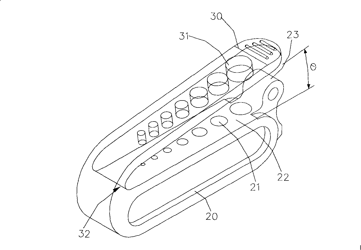
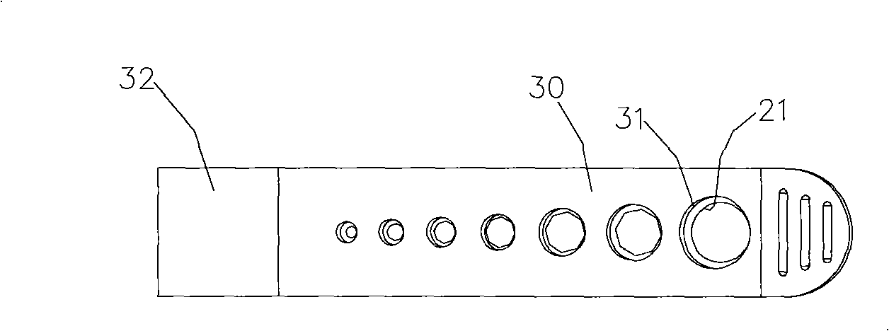
[0017] Please refer to the present invention figure 2 , image 3 ,and Figure 4 , the wrench seat structure of the present invention includes a positioning platform 20 and an outward extension arm 30, and is used with a plurality of L-shaped wrenches 40 (see Figure 5 ), its structural characteristics are:

[0018] The positioning table 20 is a one-piece assembly, and several linearly arranged through positioning holes 21 are made on a plane 22 of the positioning table 20. The shape of the positioning holes 21 corresponds to the shaft section of the L-shaped wrench 40. The positioning table 20. A protruding block 23 is made at one end of the plane 22;

[0019] The extension arm 30 is integrally connected to the other end of the plane 22 of the positioning platform 20 by the elastic section 32, and the extension arm 30 is connected to the positioning plat...


PUM


Abstract

The invention discloses a novel wrench base structure, which comprises a locating platform and an external extension arm. A locating hole and a limiting hole are correspondingly made on the locating platform and the external extension arm; one end of the external extension arm is connected with the locating platform through an elastic segment; the external extension arm is matched with the elastic segment, so as to keep the inclined external extension being positioned at the preset angle; thus, the novel wrench base structure utilizes the strength of the elastic reset inclined external extension preset angle of the external extension arm, so as to make the limiting hole of the external extension arm overlap with the locating hole on the locating platform and position the wrench passing through the locating hole and the limiting hole at the same time, thereby reducing the cost for positioning the design structure of the product.

Description

technical field [0001] The invention relates to a hand tool, in particular to a wrench seat structure. Background technique [0002] At present, due to the continuous development and improvement of the design of hand tools, the wrench tool set products that can be easily carried around have become the most convenient tool type, and various wrench tool set products have been widely used in human life and processing factories. However, there are still some technical blind spots in the wrench tool set, which are waiting for further development and improvement. [0003] Such as figure 1 As shown, generally the wrench tool sets used on the market include a plurality of L-shaped wrench tool bars 10 of different sizes and a positioning seat 11, and each L-shaped wrench tool bar 10 is passed through the positioning seat according to the size. 11 in the through hole 111, and the shape of the through hole 111 corresponds to the cross-sectional shape of the L-shaped wrench tool bar 1...

Claims


Application Information

Patent Timeline
IPC IPC(8): B25H3/00B25H3/04B25B13/00B25B23/00
Inventor 邱俞儒
Owner 邱俞儒
Learn More