Pressure-holding type pressure balancing sewer valve

A blowdown valve and balancing technology, applied to valve details, diaphragm valves, valve devices, etc., can solve problems such as limited pressure range and unusable filters

Inactive Publication Date: 2008-09-24
王克涛
View PDF0 Cites 0 Cited by
  • Summary
  • Abstract
  • Description
  • Claims
  • Application Information

AI Technical Summary

Problems solved by technology

[0002] Most of the reversing control valves of the existing laminated self-cleaning filters use diaphragm valves, which pressurize or release the pressure in the diaphragm cavity of the valve to move the diaphragm to control the opening and closing of the valve, so the diaphragm’s bearin

Method used


Image

  • Pressure-holding type pressure balancing sewer valve
  • Pressure-holding type pressure balancing sewer valve

Examples


Embodiment Construction

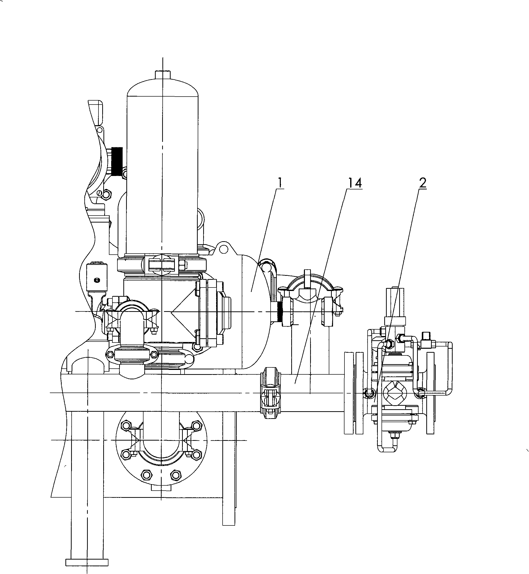
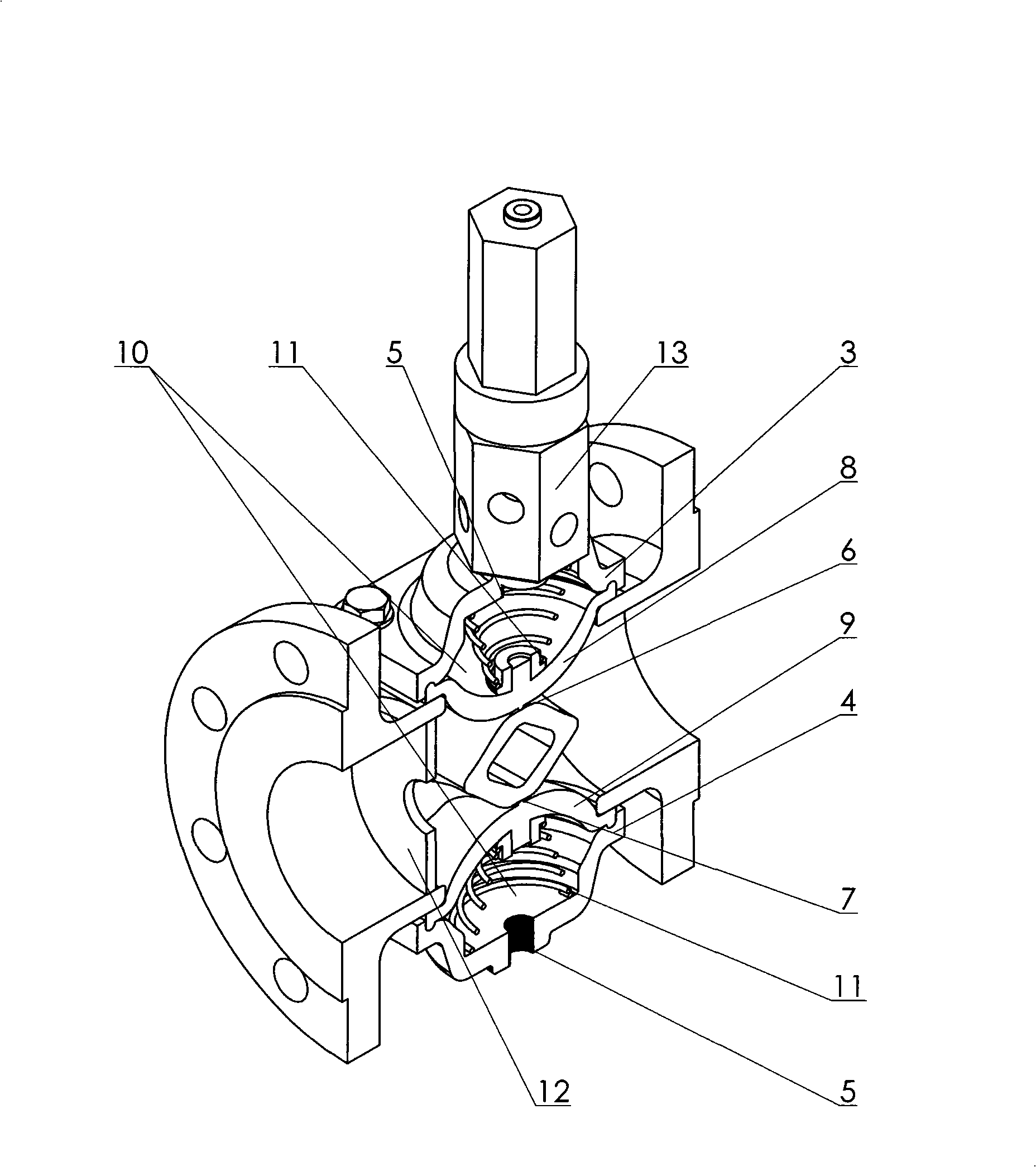
[0009] The structure of the present invention is as shown in the accompanying drawings: it is made of a pilot valve, a valve body, a valve cover, a diaphragm, and a throttling orifice. An upper valve cover 3 and a lower valve cover 4 are respectively arranged above and below the valve body, a pilot valve 13 is installed on the upper valve cover 3, and a pressure charging and pressure relief port 5 is arranged at the upper and lower valve cover upper ends. There are upper valve seat 6 and lower valve seat 7 respectively in the valve body. There is an upper diaphragm 8 and a lower diaphragm 9 between the upper and lower valve seats and the upper and lower valve covers respectively. The membrane cavity 10 formed between the diaphragm and the valve cover has an auxiliary spring 11 in each membrane cavity. A throttling orifice 12 is installed at the inlet of the valve.


PUM


Abstract

An equilibrated sewer valve of continuous pressure type belongs to the design and manufacture technical field of a laminated filter. The invention comprises a pilot valve, a valve body, a valve cover, a diaphragm and a restriction orifice. An upper valve cover and a lower valve cover are respectively arranged on and under the valve body. The upper valve cover is provided with one pilot valve. An upper valve seat and a lower valve seat are respectively arranged in the valve body. An upper diaphragm and a lower diaphragm are respectively arranged between the upper and the lower valve seats and the upper and the lower valve covers. The restriction orifice is arranged at the entrance of the valve. The equilibrated sewer valve of continuous pressure type is mounted on the blow-off pipeline of the laminated filter. The blow-off pressure different between the filter and the atmosphere is resolved into the pressure difference of the filter and the blow-off pipe and the pressure difference of the blow-off pipe and the atmosphere in order to reduce the pressure difference at the two ends of the reversing execution diaphragm of the filtering unit of the laminated filter and improve the pressure range of use of the laminated filter.

Description

technical field [0001] The invention belongs to the technical field of design and manufacture of laminated filters. Background technique [0002] Most of the reversing control valves of the existing laminated self-cleaning filters use diaphragm valves, which pressurize or release the pressure in the diaphragm cavity of the valve to move the diaphragm to control the opening and closing of the valve, so the diaphragm’s bearing The pressure determines the operating pressure of the filter, so the filter cannot be used when filtering the fluid medium conveyed by high-pressure pipelines. Therefore, the pressure range of the existing laminated filter in practical applications is limited, which is not very ideal. Contents of the invention [0003] The object of the present invention is to provide a kind of under the high-pressure environment, through the throttling and partial pressure of the valve, the reversing executive diaphragm of the filter unit of the laminated filter is ch...

Claims


Application Information

Patent Timeline
IPC IPC(8): F16K7/14F16K27/00F16K47/00F16K31/126B01D29/46
Inventor 王克涛
Owner 王克涛
Why Eureka
Try Eureka