Monochrome ink gun structure

An inkjet head and inkjet technology, applied in printing and other directions, can solve the problems of inkjet head temperature rise, inkjet head damage, price reduction, etc., achieve high-performance printing and reduce costs

Active Publication Date: 2008-10-01
MICROJET TECH
View PDF0 Cites 17 Cited by
  • Summary
  • Abstract
  • Description
  • Claims
  • Application Information

AI Technical Summary

Problems solved by technology

[0007] The existing technology is to increase the density of the intermittent lines along the advancing axis of the inkjet medium by increasing the number of heaters of the inkjet head, so as to improve the printing resolution and improve the printing speed, although increasing the number of heaters of the inkjet head It can achieve faster printing speed, but many heaters will generate a lot of heat to make the temperature of the inkjet head rise rapidly, which will not only affect the printing quality but also damage the entire inkjet head
[0008] One of the solutions developed by the industry at present is to increase the size of the inkjet head to avoid the rapid rise of the temperature of the inkjet head. However, for the highly competitive inkjet printing market, the price of inkjet printers has dropped significantly. Fast, increasing the size of the inkjet head will increase the cost of producing inkjet printers and reduce market competitiveness
[0009] And when the number of nozzle holes of the inkjet head is large, the inkjet head will be designed to be transmitted in sequence to save the number on the input / output (I / O) of the nozzle chip, but because the inkjet head chip needs to drive the heater. The control method still needs to combine address control and print data signals, but the design method for address control in the existing inkjet head chip is that when the number of addresses for controlling the heating of the inkjet head is n, the position decoder needs to be set accordingly For connecting to the corresponding inkjet drive circuit, for example, when the number of addresses for controlling the heating of the inkjet head is 20, the position decoder needs to be provided with 20 cables, but with the number of heaters The existing design will increase the area of ​​the chip and increase the size of the inkjet head, so how to reduce the way of address control is an important issue for saving the chip area

Method used


Image

  • Monochrome ink gun structure
  • Monochrome ink gun structure
  • Monochrome ink gun structure

Examples


Embodiment Construction

[0029] Some typical embodiments embodying the features and advantages of the present invention will be described in detail in the description in the following paragraphs. It should be understood that the invention is capable of various changes in different aspects without departing from the scope of the invention, and that the description and illustrations therein are illustrative in nature and not limiting. this invention.

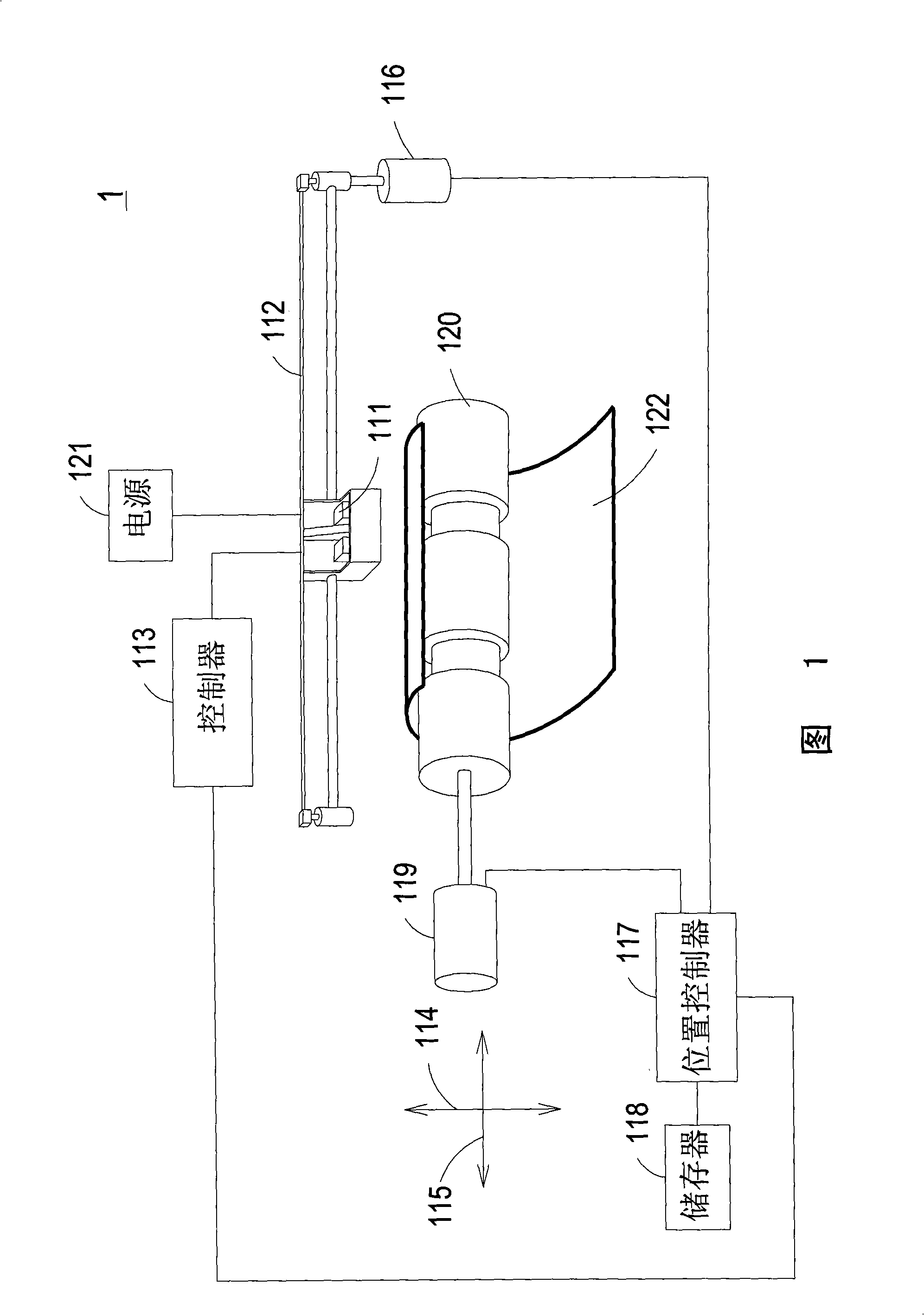
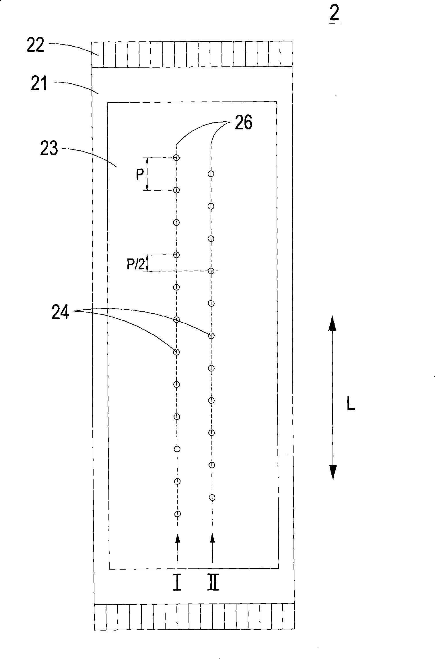
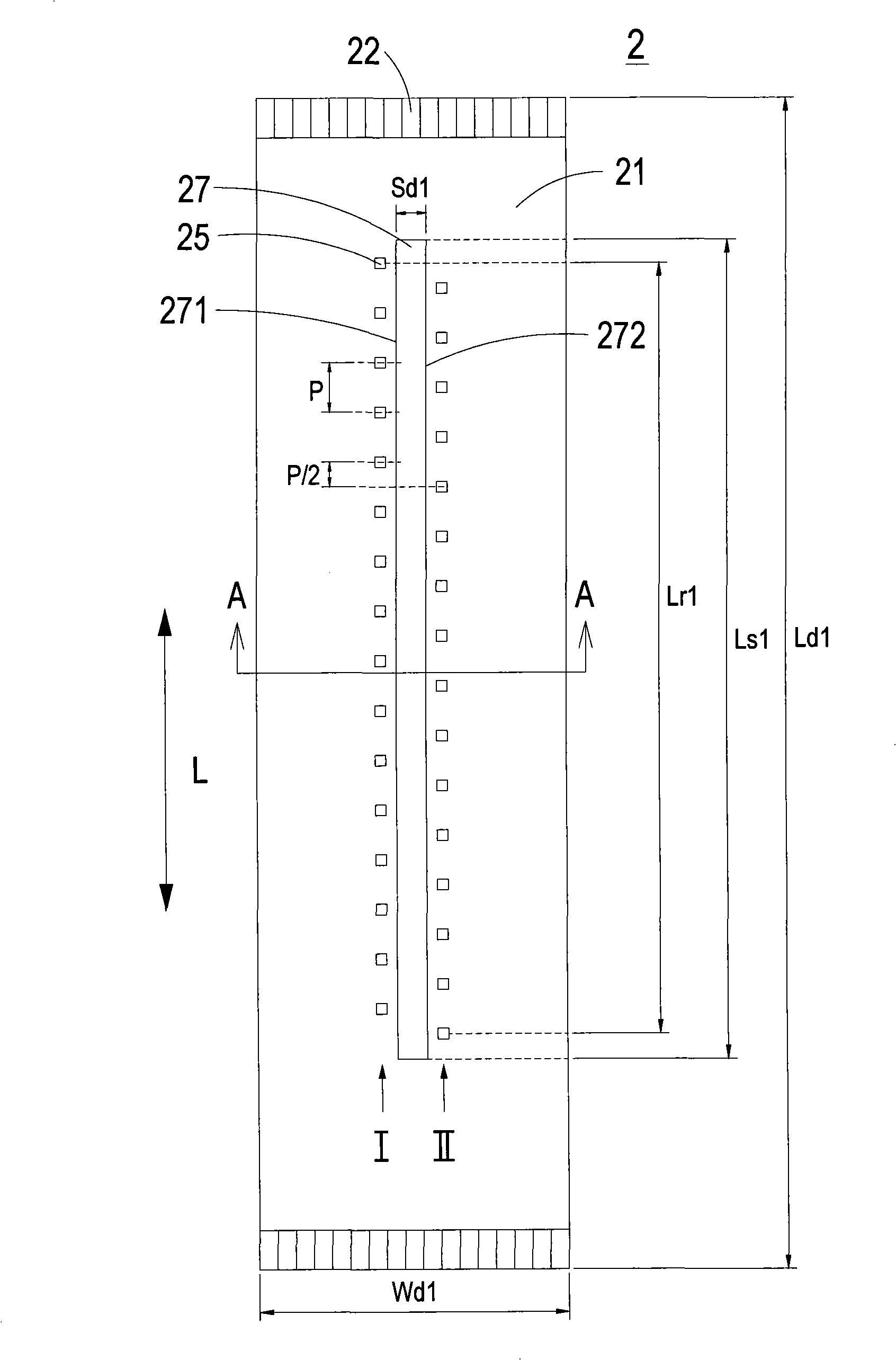
[0030] The structure of the inkjet head of the present invention mainly arranges a large number of nozzle holes on the inkjet head in a staggered manner, so as to reduce the size of the inkjet head and provide higher printing resolution with fewer scanning and printing times, that is, The effective orifice density of the inkjet medium on the feed shaft is increased to provide a high-resolution printing speed, thereby making the inkjet head structure of the present invention applicable to relatively low-cost inkjet printers.

[0031]Please refer to Fig. 1...


PUM


Abstract

The invention relates to an inkjet head structure which is used for inkjet printing with self-colored ink, comprising a chip and a plurality of heaters which are arranged on the chip with the density which is higher than the density of 14 heaters per square millimeter (mm2), furthermore, the heaters are arrayed to form at least two axis assemblies along the parallel axes with intervals.

Description

technical field [0001] The invention relates to an inkjet head structure, especially a monochrome inkjet head structure suitable for ink cartridges. Background technique [0002] In addition to laser printers, inkjet printers are another widely used type of printers currently on the market. They have the advantages of low price, easy operation, and low noise, and can print on various types of paper, such as paper and photo paper. Inkjet media. The printing quality of an inkjet printer mainly depends on factors such as the design of the ink cartridge, especially the design of the inkjet head mechanism that controls the printing chip to release ink droplets to the inkjet medium is an important consideration in the design of the ink cartridge. [0003] Generally speaking, an inkjet printer mainly uses the inkjet head to print the pattern of independent dots at a specific position of an array to combine the printed image, and the position of the independent dot is determined by...

Claims


Application Information

Patent Timeline
Patent Type & Authority Applications(China)
IPC IPC(8): B41J2/14B41J2/05
Inventor 欧享沛韩永隆黄启峰
Owner MICROJET TECH
Why Eureka
Try Eureka