Side bow conveyor chain with inner and outer chain links

A technology of conveying chain and inner chain link, applied in the direction of conveyor, drag chain, hanging chain, etc., can solve problems such as incompatibility, and achieve the effect of simple installation

Inactive Publication Date: 2008-10-01
FLEXON
View PDF4 Cites 20 Cited by
  • Summary
  • Abstract
  • Description
  • Claims
  • Application Information

AI Technical Summary

Problems solved by technology

In view of the rollers arranged horizontally and vertically, such a structur...

Method used


Image

  • Side bow conveyor chain with inner and outer chain links
  • Side bow conveyor chain with inner and outer chain links
  • Side bow conveyor chain with inner and outer chain links

Examples


Embodiment Construction

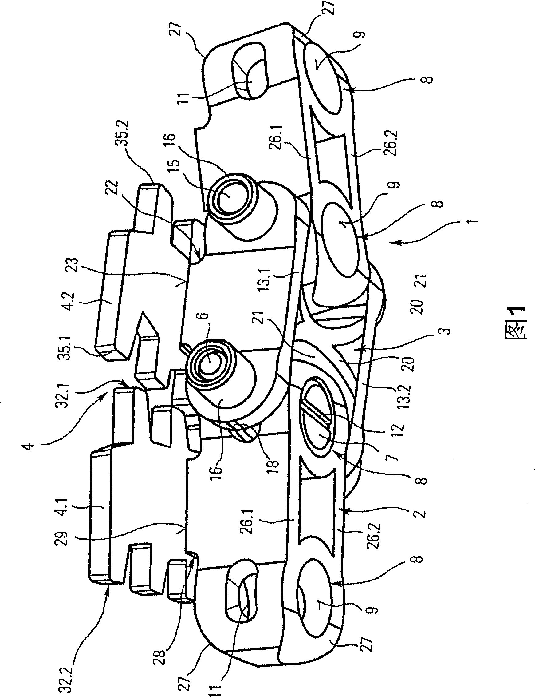
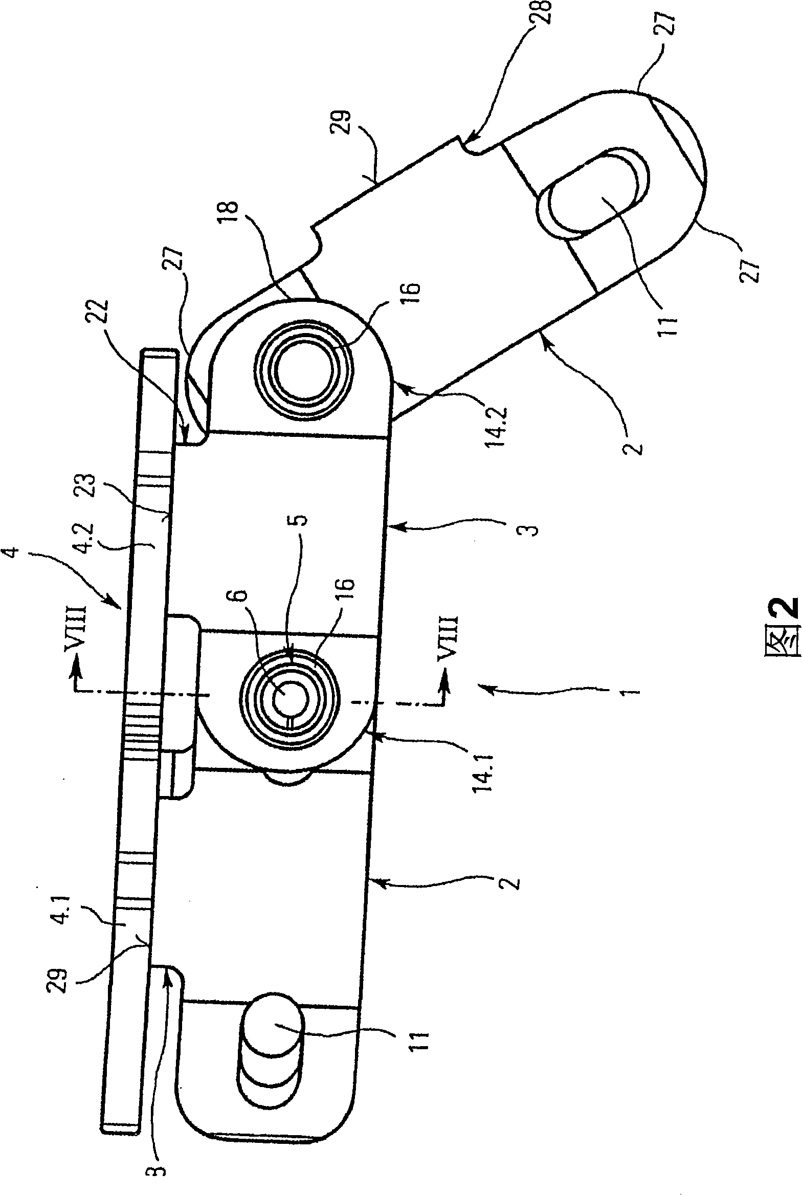
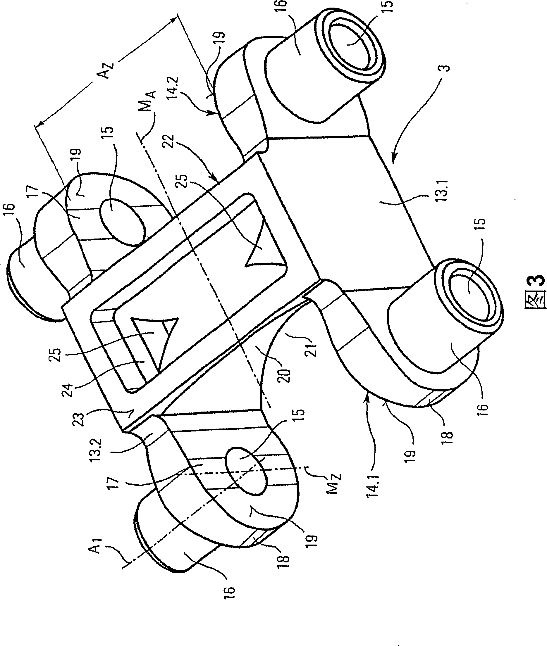
[0044] Referring to FIGS. 1 to 12 , a first embodiment of a side bending conveyor chain 1 (hereinafter referred to as: chain) according to the present invention will be described in detail. The chain 1 comprises inner links 2 and outer links 3 arranged in alternating succession, and a plate belt 4 arranged on the links 2 and 3 and defined by individual support plates 4.1 and 4.2. The connection between the inner chain link 2 and the outer chain link 3 is formed by a chain hinge 5, wherein the chain hinge 5 is arranged to be able to surround ( Figure 8 middle horizontal) first axis A 1 and around ( Figure 8 vertical) second axis A 2 pivot. Each chain hinge 5 comprises a pivot bolt 6 and a cylindrical pivot pin 7 , as well as a receiving sleeve 8 which is provided as an integral part of the inner chain link 2 and accommodates the pivot pin 7 and the pivot bolt 6 . The pivot pin 7 is arranged in a base hole 9 of the receiving sleeve 8 such that the pivot pin 7 can move arou...


PUM


Abstract

This invention provides a laterally-bent conveying chain. Chain links thereof are mutually connected by hinges which pivot around the first and second axes. The conveying chain further comprises a pivot bolt disposed along the first axis, a pivot pin that is disposed along the second axis and can be passed through by extending the pivot bolt, and a receiving sleeve extending along the second axis; characterized in that, the pivot pin may pivot around the second axis with respect to the receiving sleeve. The receiving sleeve is equipped with a transverse pivot opening for passing the pivot bolt. The stability of chain can be improved by following characteristics: inner and outer chain links are alternately and continuously arranged; the inner chain link comprises receiving sleeves located at each end thereof, and at least one inner link plate mutually connecting the receiving sleeves; the outer chain link comprises pivot bolts and pivot pins located at each end thereof, and at least two outer link plates mutually connecting the bolts and pins; and each end face of at least two outer link plates transversely encloses the receiving sleeves of adjacent inner chain links. When the chain moves forward in a straight line, the inner and outer chain links disposed vertical to edges extend in a direction vertical to the first axis.

Description

technical field [0001] The invention relates to a side bending conveyor chain, the links of which are connected to each other by a chain hinge arranged to pivot about a first and a second axis, said chain hinge comprising a pivot point arranged along said first axis an axle bolt, a pivot pin disposed along the second axis through which the pivot bolt extends, and a receiving sleeve extending along the second axis and wherein the pivot pin is disposed about the second axis relative to The receiving sleeve pivots, said receiving sleeve being provided with a transverse pivot opening allowing the passage of a pivot bolt. Background technique [0002] Chains of this type are known, for example, from DE 10151863 and DE 10207687. The first and second axes of the chains extend at right angles to each other such that there is a universal joint connection between the chain links. Individual links have respective support plates connected thereto such that all links and support plates...

Claims


Application Information

Patent Timeline
IPC IPC(8): B65G17/38F16G13/12
CPCB65G17/40B65G17/086B65G17/385
Inventor F·米切克W·扬岑J·顺皮克S·艾希霍恩K·内德尔
Owner FLEXON
Why Eureka
Try Eureka