Annular U type diaphragm for hydraulic diaphragm pump

A hydraulic diaphragm pump, annular technology, applied in the direction of pumps, pump components, variable displacement pump components, etc., can solve the problems of diaphragm stress and stress changes, inconvenient installation and maintenance, excessive deflection and deformation, etc., and achieve the deflection and deformation volume. Large, convenient installation and maintenance, the effect of prolonging the working life

Inactive Publication Date: 2010-06-02
ZHEJIANG UNIV OF TECH
View PDF6 Cites 0 Cited by
  • Summary
  • Abstract
  • Description
  • Claims
  • Application Information

AI Technical Summary

Problems solved by technology

At present, the commonly used rubber diaphragm shape is a circular flat diaphragm, figure 1 It is a schematic diagram of the assembly of a traditional circular flat diaphragm, in which, 6-plunger, 7-circular flat diaphragm, in the actual use process, the outer round edge of the circular flat diaphragm is fixed, the inner side of the diaphragm is flexed and deformed front and rear, and the front and rear deflection The deformation size is related to the deformation stress. If the deflection deformation is too large, the stress generated by the diaphragm is also large. The stress of the circular flat diaphragm reaches the maximum value at the edge of the diaphragm and the middle of the circle, so the stress of the diaphragm is easy to concentrate and easy to produce Large fluctuations in stress, so that the life of the diaphragm is relatively short
In addition, the radial dimension of the circular flat diaphragm is too large, resulting in a lot of consumables, and there is no installation slot on the circular flat diaphragm, which is inconvenient for installation and maintenance

Method used


Image

  • Annular U type diaphragm for hydraulic diaphragm pump
  • Annular U type diaphragm for hydraulic diaphragm pump
  • Annular U type diaphragm for hydraulic diaphragm pump

Examples


Embodiment Construction

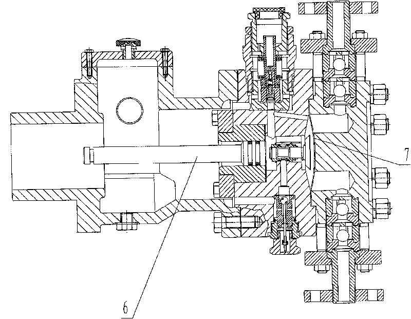
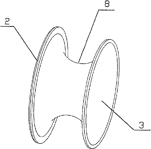
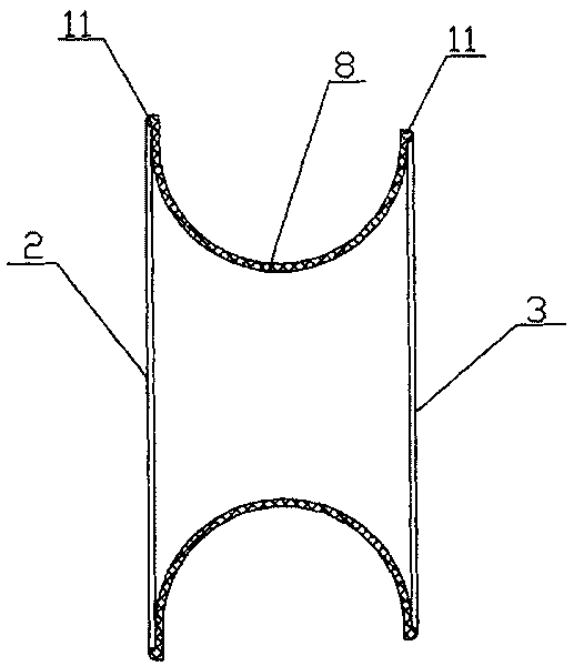
[0012] see Figure 2-4 : A kind of annular U-shaped diaphragm for a hydraulic diaphragm pump, the side wall of the annular U-shaped diaphragm is surrounded to form a hollow structure, the middle part of the annular side wall 8 is concave, and the two ends expand outwards to form a trumpet shape. The outer edge of the bell mouth 2 is liquid-tightly installed on the diaphragm chamber wall 4 of the hydraulic diaphragm pump. There is a distance between the outer edge of the bell mouth 3 at the other end and the diaphragm chamber wall 4, and the bell mouth 3 at the other end The diaphragm plate 1 that is liquid-tightly matched with it is installed on the top, and the diaphragm plate 1 cooperates with the annular U-shaped diaphragm to separate the diaphragm cavity of the hydraulic diaphragm pump into the inner part of the annular side wall 8 and the diaphragm plate 1. The oil chamber 9 and the medium chamber 10 located outside the annular side wall 8 and the diaphragm plate 1.

[0...


PUM


Abstract

The invention relates to a ring-shaped U type diaphragm for a hydraulic diaphragm pump, the side wall of the ring-shaped U type diaphragm surrounds and forms a hollow structure, the middle part of thering-shaped side wall is concave, the two ends extend outwards and form a horn shape, the outer edge of the horn mouth on one end is liquid-sealedly mounted on the diaphragm cavity wall of the hydraulic diaphragm pump, the outer edge of the horn mouth on the other end is distant from the diaphragm cavity wall, the horn mouth on the other end is equipped with a diaphragm plate liquid-sealedly matched therewith, the diaphragm plate combines with the ring-shaped U type diaphragm to divide the hydraulic diaphragm pump into an oil cavity on the ring-shaped side wall and the inside of the diaphragmplate and a medium cavity on the outside of the ring-shaped side wall and the diaphragm plate. The invention provides a ring-shaped U type diaphragm for a hydraulic diaphragm pump, which has long service life, reduced radial size and little material consumption, and is easy to install and maintain.

Description

technical field [0001] The invention relates to a diaphragm for a hydraulic diaphragm pump. Background technique [0002] Due to the characteristics of high pressure, high efficiency, energy saving, no leakage, zero pollution, long life, and high reliability, hydraulic diaphragm pumps are widely used in various industries such as petroleum, chemical industry, food, medicine, electric power, and water treatment. Quantitative delivery of flammable, explosive, toxic, corrosive or non-corrosive media. The hydraulic diaphragm pump uses a rubber diaphragm to separate the conveying medium from the driving medium (oil). The reciprocating motion of the piston acts on the rubber diaphragm through the transmission of the oil medium, making the rubber diaphragm concave and convex, and completing the suction and discharge of the slurry. This kind of pump not only prevents the conveying medium from leaking out, but more importantly, it prevents the conveyed granular medium from contactin...

Claims


Application Information

Patent Timeline
Patent Type & Authority Patents(China)
IPC IPC(8): F04B53/00F04B43/067
Inventor 张生昌邓鸿英郑水华张华军王祺张金海
Owner ZHEJIANG UNIV OF TECH
Why Eureka
Try Eureka