Orientation sheet-supporting structure of thin type speaker

A technology for positioning the support piece and the speaker, which is applied in the direction of fixing/tightening of the diaphragm, which can solve the problems of hindering the normal sound of the speaker, collision between the sound cone and the positioning support piece, etc., to reduce the resonance frequency, increase the displacement distance, and improve the low frequency. effect of response

Active Publication Date: 2011-09-14
WUXI JIEFU ELECTROACOUSTIC
View PDF0 Cites 0 Cited by
  • Summary
  • Abstract
  • Description
  • Claims
  • Application Information

AI Technical Summary

Problems solved by technology

However, the traditional positioning support piece connects the basin frame and the sound cone. Since the sound cone is flat to a certain extent, when the speaker is working, it will cause the sound cone to collide with the edge of the positioning support piece, hindering the normal sound production of the speaker.

Method used


Image

  • Orientation sheet-supporting structure of thin type speaker
  • Orientation sheet-supporting structure of thin type speaker

Examples


Embodiment Construction

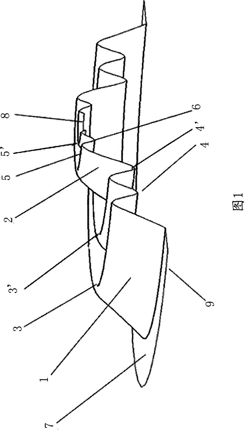
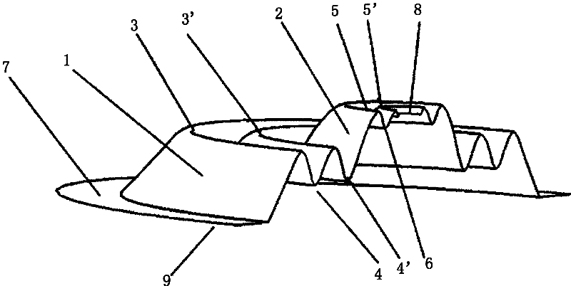
[0011] figure 1 What is shown is a structure with only 4 crests forming two bosses, and of course a structure larger than two bosses can also be designed according to requirements.

[0012] As shown in the figure: there is a wave-shaped positioning support piece 9 with a cross-section, based on the annular flat plate 7 at the edge, the upper surface of the annular flat plate 7 is extended and arched upwards, forming the first crest 3, and the face of the first crest 3 is inclined downward. Extending to form the first wave trough 4, the surface of the first wave trough 4 is extended upwards to form the second wave peak 3', and the second wave peak 3' is extended downward to form the second wave trough 4'; so repeated, several wave peaks and wave troughs can be formed . The first crest 3 and the second crest 3' form the first boss 1, the surface of the second trough 4' extends obliquely upwards to form a third crest 5, and the face of the third crest 5 extends downward to form ...


PUM


Abstract

The present invention provides a location supporting plate of the loudspeaker, also named as a center suspension or an elasticity wave, in particular a thin loudspeaker location supporting plate structure. According to the design of the invention, the section of the location supporting plate shows a wave shape, a center hole is mounted in the center of the location supporting plate, each wave comprises a wave trough and a peak respectively, and the height of the peak is higher than the height of the wave; a projecting platform is composed of one peak, or two more peaks having similar or same heights; the projecting platform at least has two; and height of the projecting platform near the center is higher than the heights of the rest projecting platforms. The location supporting plate of the loudspeaker employs a multiple projecting platforms structure, especially fit for audio pattern design of plate video devices such as LCD, PDP and the like. The invention improves the compliance ofthe location supporting plate or the whole loudspeaker vibration system, thereby effectively reducing the resonant frequency of the loudspeaker, improving the low frequency response.

Description

technical field [0001] The invention relates to a loudspeaker positioning strut, also known as a centering strut or a spring wave, in particular to a thin loudspeaker positioning strut structure suitable for high-power full-frequency loudspeakers. Background technique [0002] Nowadays, high-power full-range speakers used in LCD, PDP and other flat-panel video equipment generally use flatter speaker frames and cones in order to make the structure of the entire speaker unit thinner. However, the traditional positioning support piece connects the basin frame and the sound cone. Since the sound cone is flat to a certain extent, when the speaker is working, the sound cone will collide with the edge of the positioning support piece, which hinders the normal sound generation of the speaker. Therefore, only by designing a novel positioning support piece structure can the requirements of high power and thin structure of the loudspeaker used in flat-panel video equipment be met. Co...

Claims


Application Information

Patent Timeline
Patent Type & Authority Patents(China)
IPC IPC(8): H04R7/16
Inventor 蒋加星
Owner WUXI JIEFU ELECTROACOUSTIC
Why Eureka
Try Eureka