Lead screw transmission lifting rod

A technology of screw drive and lifting rod, which is applied to lifting frames, lifting devices, antenna supports/installation devices, etc., can solve the problems of difficulty in controlling the stability of the rod body, long erection time, easy to cause harm, etc., and save manpower. , The effect of good anti-icing performance and short lifting time

Active Publication Date: 2011-04-20
南京俊东机电设备有限公司
View PDF0 Cites 1 Cited by
  • Summary
  • Abstract
  • Description
  • Claims
  • Application Information

AI Technical Summary

Problems solved by technology

[0004] 2. The lifting process is easy to get stuck, and the failure rate is high
[0005] 3. The casings are lifted and lowered step by step, and the lifting speed is slow
[0006] 4. There is no power in the process of descending, relying on its own weight to descend, it is easy to cause harm
[0007] 5. Wind rope needs to be pulled after lifting and inversion, which takes a long time to erect
[0008] 6. The structure is complex, the cost is high, and the stability of the rod body is not easy to control

Method used


Image

  • Lead screw transmission lifting rod
  • Lead screw transmission lifting rod
  • Lead screw transmission lifting rod

Examples


Embodiment Construction

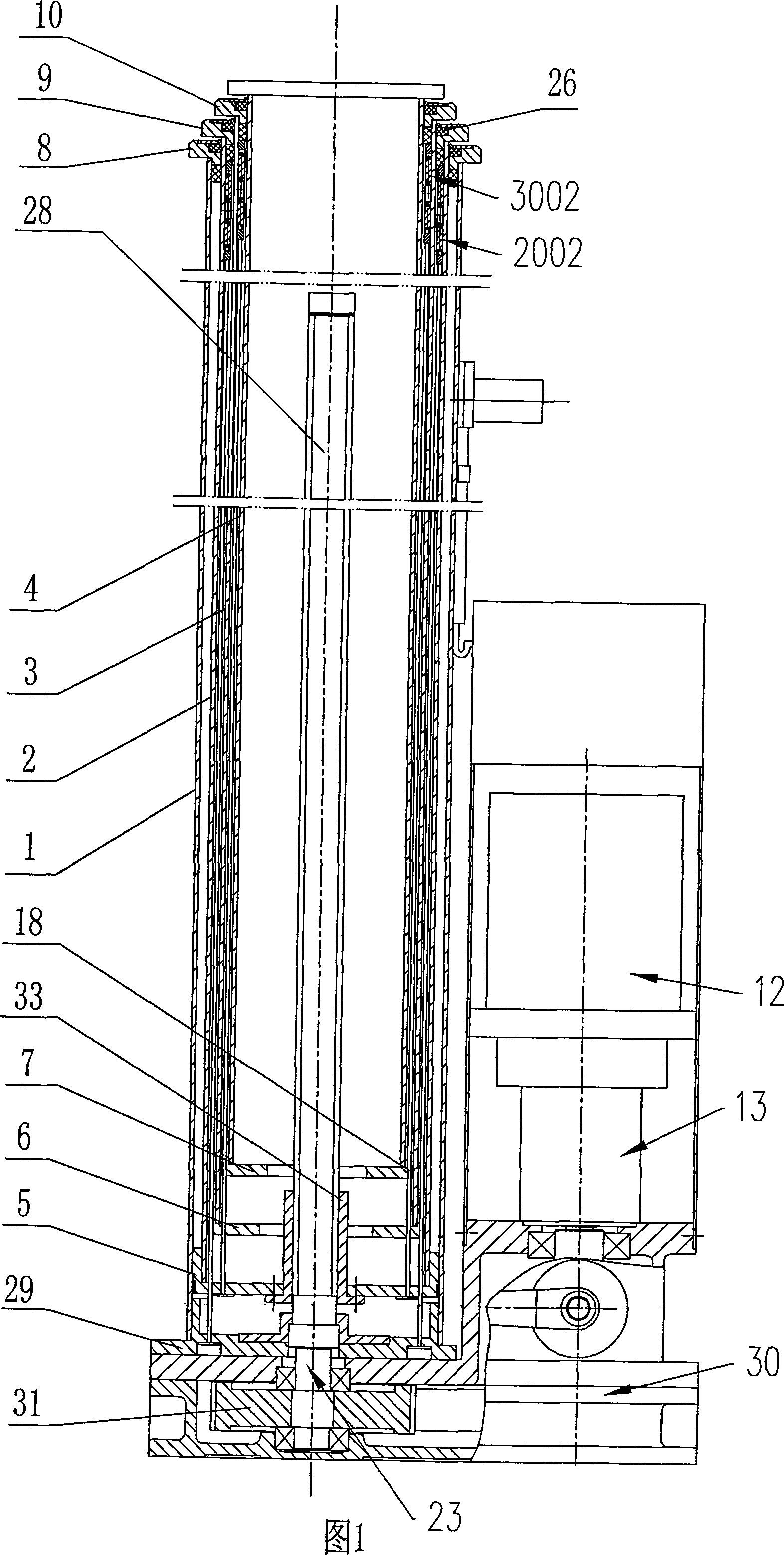
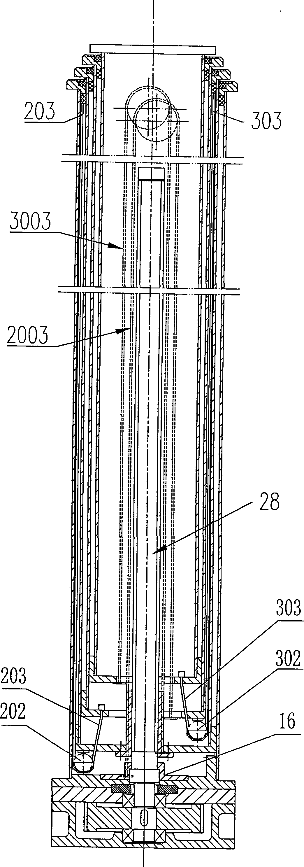
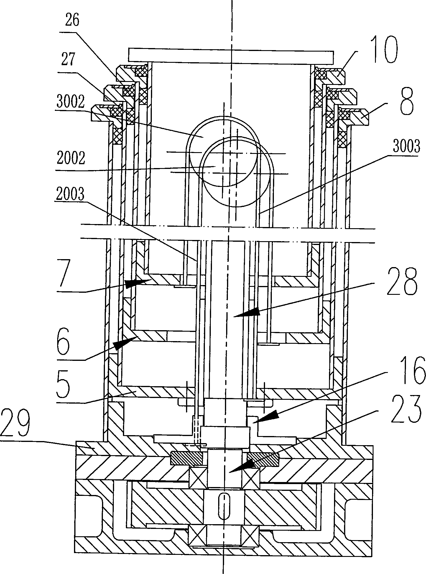
[0044] As shown in the figure, the lifting rod driven by the screw rod is stacked sequentially from the outside to the inside of the first casing 1, the second casing 2, the third casing 3, and the fourth casing 4; the adjacent casings are coaxial Swipe to connect. The bottom of the first casing 1 is set on the base 29 . The lower ends of the second bushing 2, the third bushing 3, and the fourth bushing 4 are fixedly connected with square sockets 5, 6, and 7, and the four corners of the outer walls of each socket are equipped with friction fits on the inner walls of the adjacent outer casings. Friction plate 18.

[0045] Top seals 8, 9, and 10 are respectively connected to the upper ends of the first casing 1, the second casing 2, and the third casing 3, and the inner side of each top seal is installed with a sealing ring 26 in contact with the outer wall of the adjacent inner casing; The sealing ring 26 is pressed on the top seal with a cover plate. Friction plates 27 are ...


PUM


Abstract

The invention aims at providing a screw mandrel transmission synchronous lifting rod which has relative displacement simultaneously between each casing pipe when the rod rises and identical velocity of displacement of rising and high rising speed. The lifting rod comprises that: casing pipes (1, 2, ..., n) are overlapped and sheathed from the external to the internal; the bottom of the casing pipe (1) is arranged on a pedestal; the screw mandrel and the screw nut pass through the casing pipes; the screw nut is fixedly connected with the casing pipe (2); the screw mandrel forms fixed connection with the pedestal along the radial direction of the screw mandrel and forms rotary connection with the pedestal along the circumferential direction of the screw mandrel; a driving device is connected with the screw mandrel so as to drive the screw mandrel to rotate; a pulling fixed pulley is arranged on the casing pipe (i); two ends of an upper pull rope rounding the upper pulling fixed pulley are respectively connected with the casing pipes (i-1 and i+1); when the casing pipe (i) slides upward, the casing pipe (i+1) is driven to slide upward by the upper pulling fixed pulley and the upper pull rope; i is equal to 2, 3, ..., n-1.

Description

technical field [0001] The invention relates to a lifting rod driven by a screw rod, in particular, a synchronous lifting rod driven by a square screw rod. technical background [0002] At present, the lifting poles used for erecting antennas and other loads include round tubular steel wire rope traction lifting poles and square tubular screw drive lifting poles, but they all have obvious deficiencies: [0003] 1. After the lifting rod stops randomly at a certain height, it is prone to slide down and displace, which is inconvenient to work stably at any height of the lifting rod. [0004] 2. It is easy to get stuck during the lifting process, and the failure rate is high. [0005] 3. The casings are raised and lowered step by step, and the lifting speed is slow. [0006] 4. There is no power during the descent process, and the descent depends on its own weight, which is likely to cause harm. [0007] 5. After the lifting and inversion, the wind rope needs to be pulled, an...

Claims


Application Information

Patent Timeline
Patent Type & Authority Patents(China)
IPC IPC(8): B66F7/00B66F3/10H01Q1/12
Inventor 顾华俊严六妹
Owner 南京俊东机电设备有限公司
Why Eureka
Try Eureka