Automatic positioning coil winder

An automatic positioning and reel technology, which is applied to the arrangement of the take-up reel/photosensitive drum, and the device that can bend the lead wire. The problem of messy knots and shortening the service life of the reel can achieve the effect of avoiding collision, stable and reliable multi-point positioning, and long service life.

Active Publication Date: 2008-10-08
洪子敬
View PDF0 Cites 17 Cited by
  • Summary
  • Abstract
  • Description
  • Claims
  • Application Information

AI Technical Summary

Problems solved by technology

[0003] The increasing number of electronic products has brought new enjoyment to people's life, and most electronic products have transmission lines. The transmission lines of electronic products are easy to be knotted and messy when they are stored and carried, which makes users feel inconvenient. In order to be neat and safe , It is often necessary to adjust the length of the transmission line. The use of the wire reel relatively improves this situation. Unfortunately, the conventional wire reel, when the runner rotates, the brake part moves relatively in the runner guide groove, changing the movement The direction must be assisted by the raised steps at the bottom of the guide groove of the runner to complete, resulting in frequent impacts and rhythmic impact sounds. The instantaneous impact stress generated by such frequent impacts makes the guide grooves and brake parts prone to damage , which greatly shortens the service life of the reel, which is a problem that the original designer does not want to see but cannot avoid and solve

Method used


Image

  • Automatic positioning coil winder
  • Automatic positioning coil winder
  • Automatic positioning coil winder

Examples


Embodiment Construction

[0018] The following preferred embodiments of the automatic positioning cord reel of the present invention do not limit the scope of protection of the present invention.

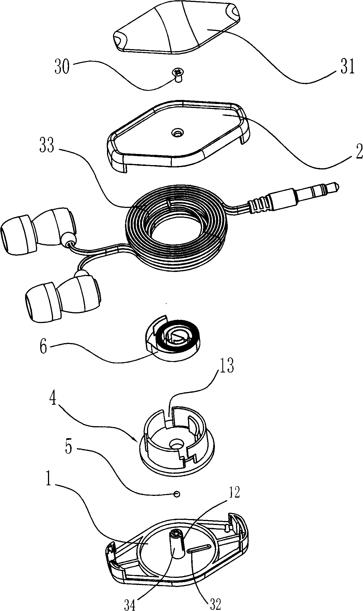
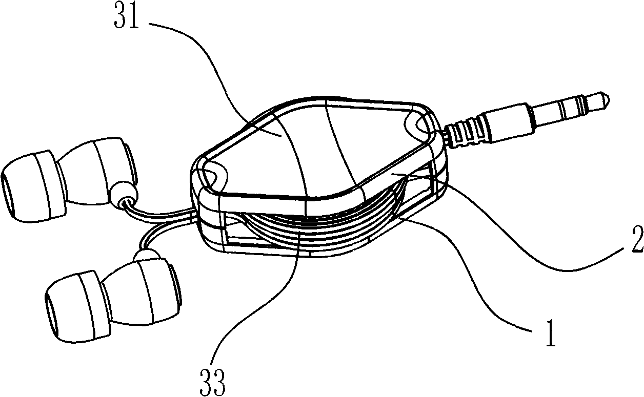
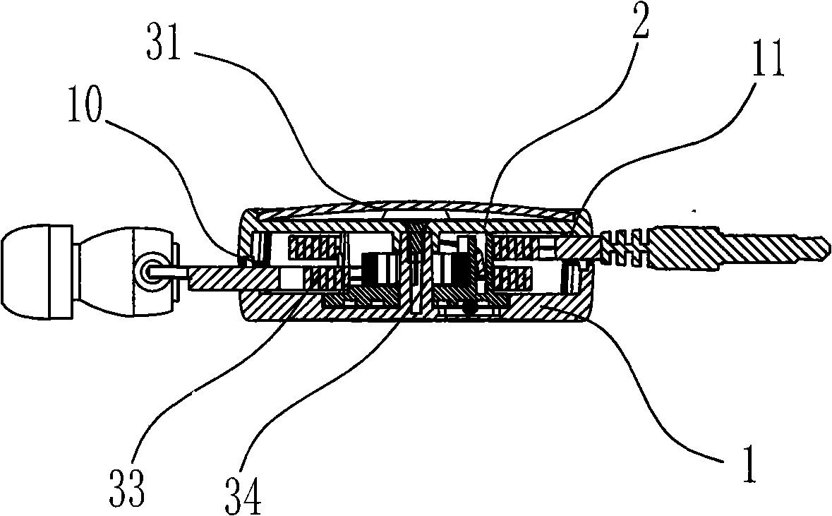
[0019] refer to figure 1 , figure 2 , image 3 , Figure 4 , Figure 5 , providing an automatic positioning cord reel, including a lower cover 1, an upper cover 2 fixedly connected to the lower cover 1, a cord winding device 3 arranged between the lower cover 1 and the upper cover 2, and a cord reel 3 arranged between the lower cover 1 and the upper cover 2 The wire inlet and outlet holes 10 on one side wall, and the wire inlet and outlet holes 11 on the other side wall, the wire winding device 3 is a center column 34 arranged at the center of the upper part of the lower cover 1, and a runner sleeved on the center column 34 4. The brake member 5 installed on the upper part of the lower cover 1 is composed of a vortex spring 6 arranged in the runner 4. The bottom of the runner 4 has an annular groove 7,...


PUM


Abstract

The invention discloses an automatic positioning winder which comprises a lower cover, an upper cover fixed connecting with the lower cover, a winding device arranged between the lower cover and the upper cover, in and out line holes arranged in one side and the other side of the upper cover and the lower cover, the winding device is composed of a center post arranged in the center of the lower cover top part, a rotating wheel sleeved on the center post, a brake component mounted on the lower cover top part, a vortex spring arranged in the rotating wheel, a ring-shaped device is provided in the bottom of the rotating wheel, the bottom of the ring-shaped groove is a plane, a positioning device separing the ring-shaped groove into guide groove is provided in the ring-shaped groove, the brake component can be embeded into the guide groove and can move relatively along the guide groove when rotating the rotaing wheel. When transmission line works for flex, the invention has advantages of soft, smooth hand feeling, silent mute effect, steady and reliable multipoint positioning, and ultra-long useful life.

Description

[0001] Technical field [0002] The invention relates to the technical field of wire winders, and more specifically relates to an automatic positioning wire winder that can manually pull out the wire and automatically rewind it. Background technique [0003] The increasing number of electronic products has brought new enjoyment to people's life, and most electronic products have transmission lines. The transmission lines of electronic products are easy to be knotted and messy when they are stored and carried, which makes users feel inconvenient. In order to be neat and safe , It is often necessary to adjust the length of the transmission line. The use of the wire reel relatively improves this situation. Unfortunately, the conventional wire reel, when the runner rotates, the brake part moves relatively in the runner guide groove, changing the movement The direction must be assisted by the raised steps at the bottom of the guide groove of the runner to complete, resulting in fr...

Claims


Application Information

Patent Timeline
Patent Type & Authority Applications(China)
IPC IPC(8): H02G11/02H01R13/72
CPCH01R13/72B65H75/4434B65H2701/34H02G11/02H04R1/1033
Inventor 洪子敬贺力之
Owner 洪子敬
Why Eureka
Try Eureka