Slide-wire resistor

A technology of sliding wire resistance and resistance wire, which is applied in the direction of sliding contact resistors, resistance terminals/electrodes, etc., can solve the problems of severe wear and reduced service life of sliding wire resistance, and achieve small wear, prolong service life, and precise control The effect of a change in resistance

Inactive Publication Date: 2012-12-05
TAIZHOU SHUANGYU ELECTRONICS
View PDF0 Cites 2 Cited by
  • Summary
  • Abstract
  • Description
  • Claims
  • Application Information

AI Technical Summary

Problems solved by technology

The disadvantage is that the slider and the resistance wire layer are connected through close conta

Method used


Image

  • Slide-wire resistor
  • Slide-wire resistor

Examples


Embodiment Construction

[0011] The following descriptions are only preferred embodiments of the present invention, and therefore do not limit the protection scope of the present invention.

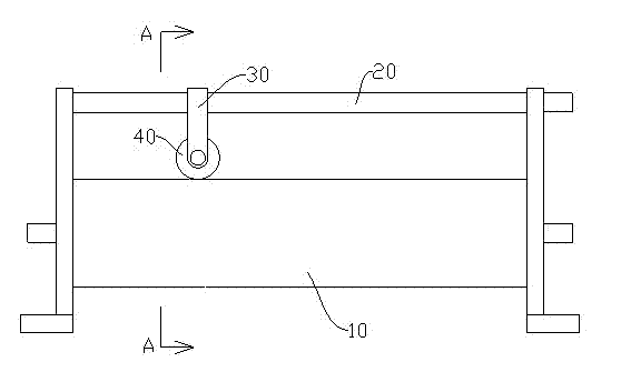
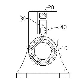
[0012] Examples, see figure 1 and figure 2 As shown: the sliding wire resistance, including the resistance wire layer 10 and the guide rail 20, of course, the resistance wire layer 10 and the guide rail 20 are respectively connected with terminals. Wherein, a slide bar 30 is provided on the guide rail 20 , and a contact wheel 40 is provided at the lower end of the slide bar 30 , and the contact wheel 40 is matched with the resistance wire layer 10 . That is, the edge of the contact wheel 40 is in close contact with the resistance wire layer 10 , so as to realize the electrical connection between the contact wheel 40 and the resistance wire layer 10 . At the same time, the guide rail 20, the slide bar 30, and the contact wheel 40 are electrically connected. Of course, the slide bar 30 is not rotatable relative...


PUM


Abstract

The invention discloses a slide-wire resistor which comprises a resistance wire layer and a lead rail, wherein a sliding rod is arranged3on the lead rail and provided with a contact wheel at the lower end; the contact wheel is in match with the resistance wire layer; and moreover, the lead rail, the sliding rod and the contact wheel are electrically connected. Preferentially, the edge of the contact wheel is in shape of a pointed cone. The slide-wire resistor has the advantages that the service life of the slide-wire resistor is relatively long, and the resistance variation precision is relatively high.

Description

technical field [0001] The invention relates to the technical field of electronic components, in particular to a sliding wire resistor. Background technique [0002] Sliding wire resistors are electronic components commonly used in laboratories and power systems. Generally, the sliding wire resistance includes a ceramic tube and a guide rail, and a resistance wire layer is wound on the ceramic tube, and a slider is provided on the guide rail. In this way, through the displacement of the slider on the resistance wire layer, the change of the resistance value between the terminal connected to the guide rail and the terminal connected to the resistance wire layer is realized. The disadvantage is that the slider and the resistance wire layer are connected through close contact, and the wear between the two is serious, which reduces the service life of the resistance wire. Therefore it is necessary to improve it. Contents of the invention [0003] In view of the shortcomings...

Claims


Application Information

Patent Timeline
IPC IPC(8): H01C10/38H01C1/14
Inventor 阮献忠
Owner TAIZHOU SHUANGYU ELECTRONICS
Why Eureka
Try Eureka