Electric stapler

A stapler and electric technology, applied in the direction of nailing U-shaped nail tools, nailing tools, manufacturing tools, etc., can solve the problems of relative position accuracy deterioration, binding ability decline, staple deformation, etc., and achieve easy disassembly steps Understand, manage and store the effect of easy and efficient molding/punching

Inactive Publication Date: 2008-10-08
MAX CO LTD
View PDF7 Cites 8 Cited by
  • Summary
  • Abstract
  • Description
  • Claims
  • Application Information

AI Technical Summary

Problems solved by technology

If there is no margin in the front-back direction width of the staple ejection path relative to the diameter of the staple, the frictional resistance when the staple is ejected will increase and the binding ability will decrease.
In addition, if the margin is too large, the posture of the staple will be disturbed when it is ejected, and the failure of the staple to be deformed and blocked in the ejection passage will easily occur.
Therefore, the relative position of the staple outlet on the staple cartridge side of the main body and the staple ejection mechanism composed of the forming part, anvil, driver, etc. requires high precision, but due to the forming tolerance and assembly error of the parts, And it is easy to produce deviation, and there is also the possibility that the relative position accuracy will deteriorate when the staple ejection mechanism is partially disassembled or replaced for maintenance.

Method used


Image

  • Electric stapler
  • Electric stapler
  • Electric stapler

Examples


Embodiment

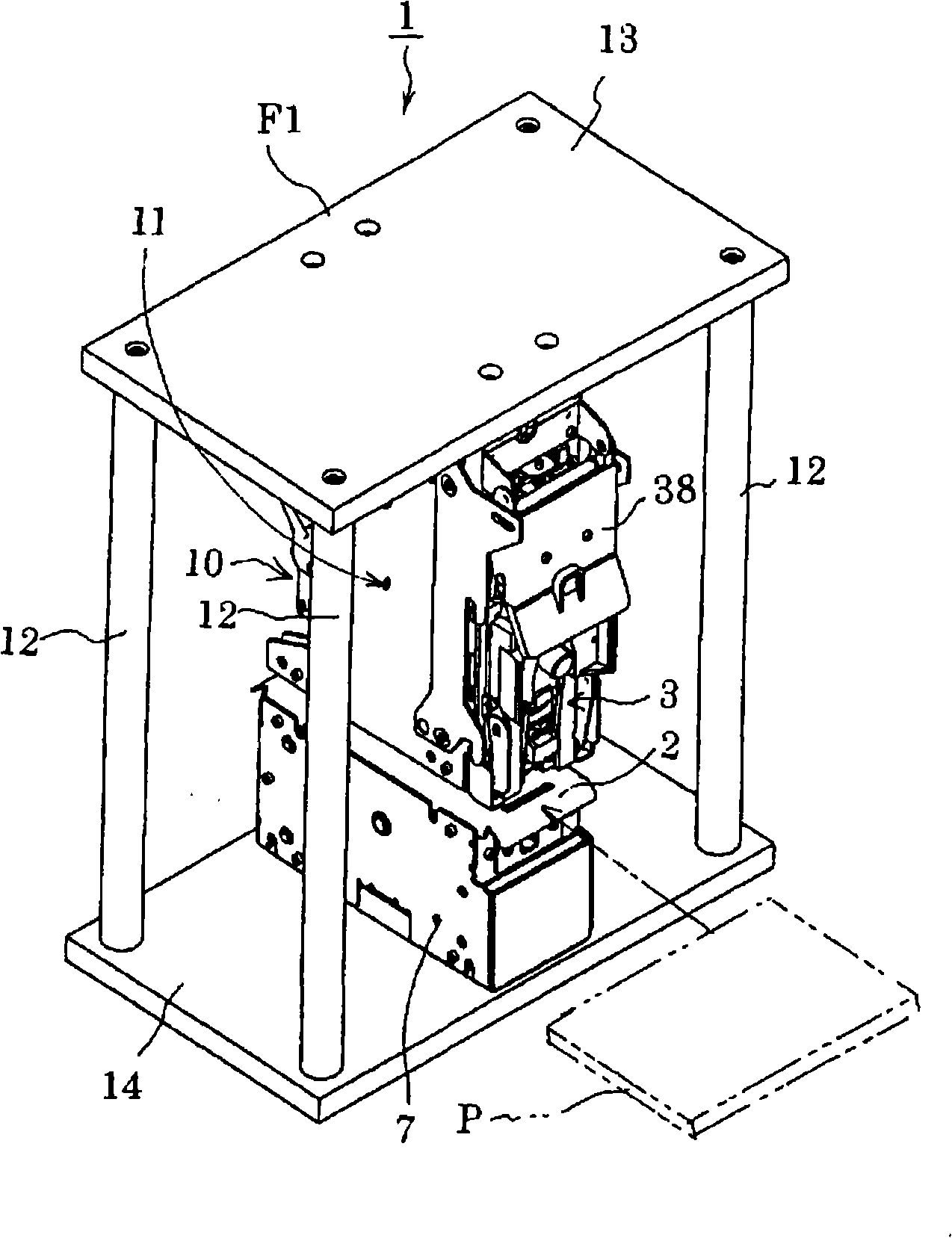
[0173] Below, refer to Figures 1 to 22B An embodiment of the present invention will be described. In the electric stapler 1 of the embodiment, the paper P is placed on the paper table 2, and the forming part 4, the driver part 5, and the slider part 6 constituting the driver assembly 3 are lowered and moved to the lower side of the jaw part 7. The driver plate 9 of the driver part 5 drives out the needle S formed by the forming plate 8 of the forming part 4 and makes it penetrate the paper P, and folds the legs of the needle S with the movable clamp (not shown) of the clamp part 7. bend.

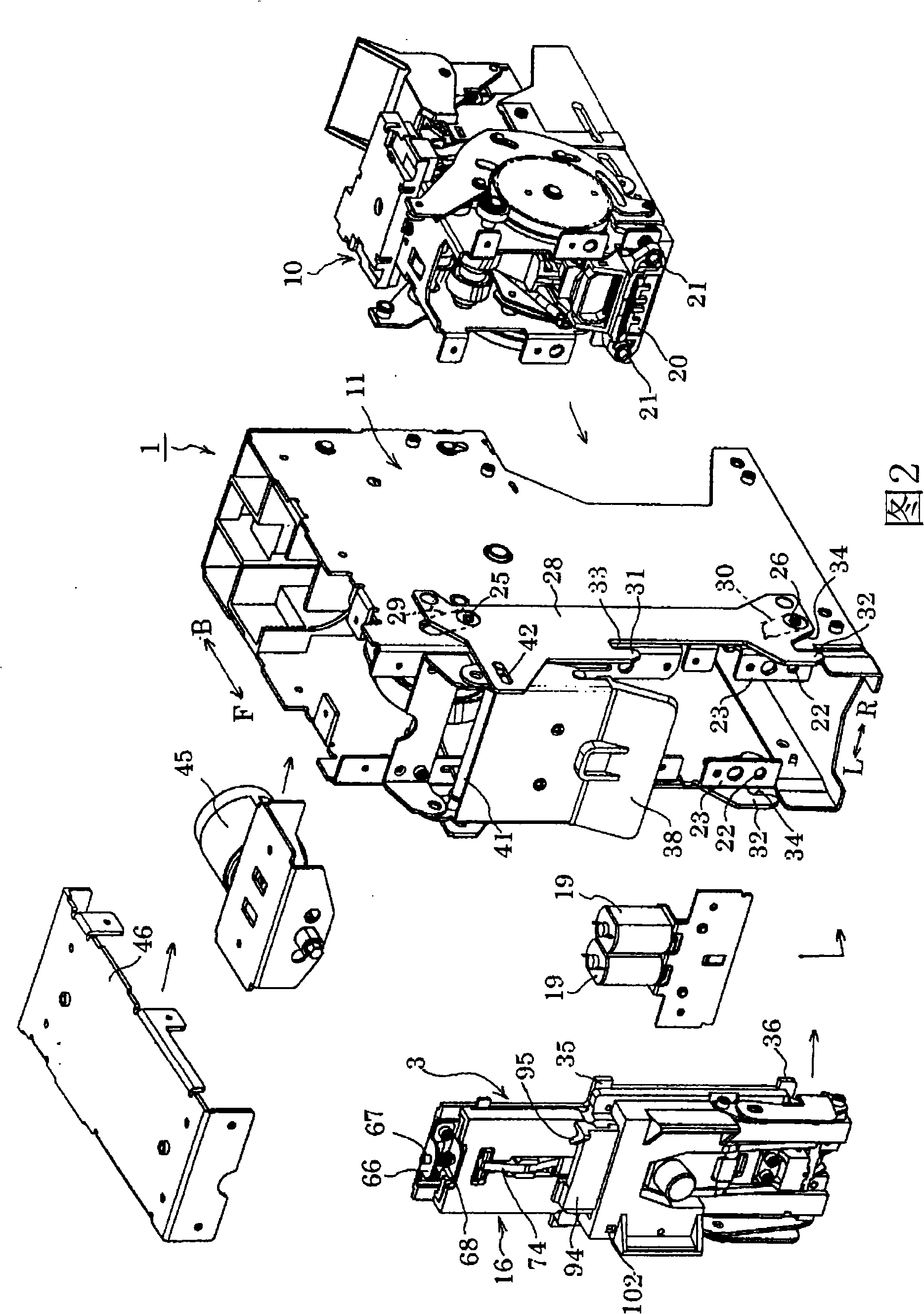
[0174] In one embodiment of the present invention, a driving rod is used to drive the slider part 6 and the driver part 5 that the action stroke is close to, on the slider part 6, so that the upper end and the lower end of the slider latch 74 can be aligned with The front surfaces of the driver parts 5 and 17 are in contact with each other at predetermined positions, and long holes 82 and...


PUM


Abstract

An electric stapler includes a stapler main body and a driver assembly which is attachable and detachable with respect to the stapler main body. The driver assembly includes a forming portion having a forming plate for forming a staple into a U shape, a driver portion having a driver plate for striking the U-shaped staple into papers, a slide block portion which slidably guides the driver portion, and a slide guide case portion. The slide block portion, the driver portion and the forming portion are integrally incorporated in the slide guide case portion.

Description

technical field [0001] The invention relates to an electric stapler. Background technique [0002] Japanese Patent Application Laid-Open No. 2005-022079 discloses the following electric stapler: the forming part with the forming plate, the driver part with the driver plate, and other anvils, top plates, etc. are separated by the paper table and the movable clamp. The clamping parts are relatively arranged. In this electric stapler, the forming part and the driver part are moved to the side of the nipper part, the needle is bent into a U shape by the forming plate, the needle is driven out by the driver plate, and the foot of the needle penetrates the paper on the paper table. The movable clamp bends the legs to bind the paper. [0003] In the above-mentioned electric stapler, the driver unit including the driver plate and the forming plate, the forming unit, and other parts such as an anvil block and a top plate are configured separately from each other. Therefore, when p...

Claims


Application Information

Patent Timeline
Patent Type & Authority Applications(China)
IPC IPC(8): B27F7/21
Inventor 八木信昭
Owner MAX CO LTD
Why Eureka
Try Eureka