Dismantlement tool for piston rings of engines and production method of dismantlement tool

A technology for disassembling tools and piston rings, which is applied to manufacturing tools, hand-held tools, etc., can solve the problems of difficulty in disassembling piston rings, inconvenient maintenance of engines, etc., and achieves the effects of simple structure, simple and practical cost, and convenient maintenance.

Inactive Publication Date: 2012-07-25
DONGGUAN LIYU GAS POWER
View PDF6 Cites 10 Cited by
  • Summary
  • Abstract
  • Description
  • Claims
  • Application Information

AI Technical Summary

Problems solved by technology

[0003] At present, the dismounting tools for engine piston rings are conventional dismounting tools. Because the piston rings are processed by alloy materials and have strong elasticity, it is very difficult for conventional dismounting tools to disassemble the piston rings, which leads to engine maintenance. inconvenient

Method used


Image

  • Dismantlement tool for piston rings of engines and production method of dismantlement tool
  • Dismantlement tool for piston rings of engines and production method of dismantlement tool
  • Dismantlement tool for piston rings of engines and production method of dismantlement tool

Examples


Embodiment 1

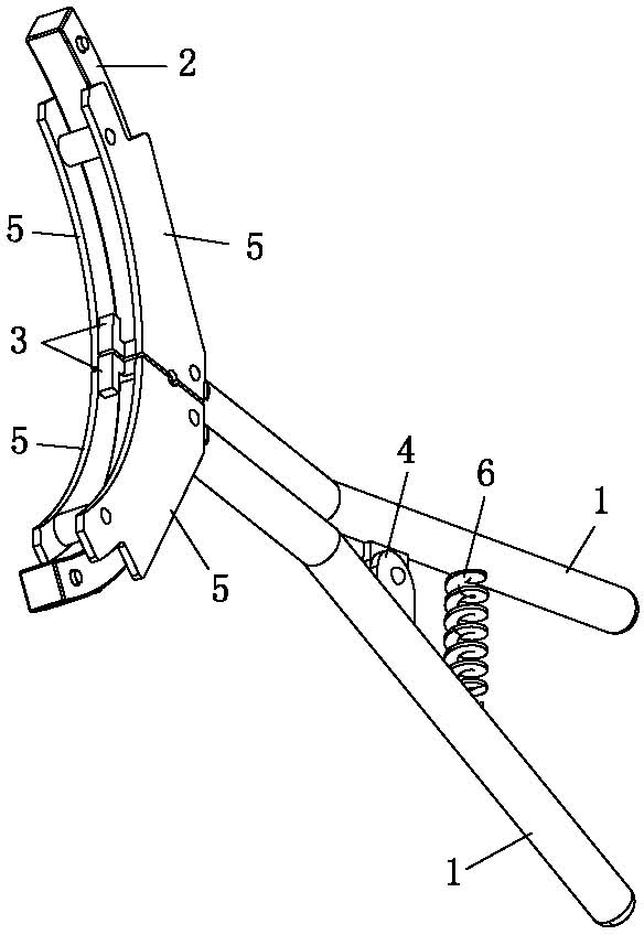
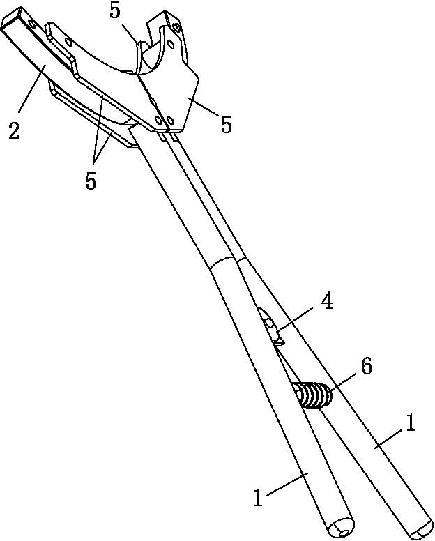
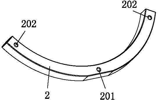
[0045] See Figure 1 to Figure 6 . A dismantling tool for an engine piston ring of the present embodiment includes a handle 1, a gland plate 5, an arc guide block 2 and a positioning claw 3; there are four gland plates 5, and every two pieces are fixed parallel to each other as a group. And between each group of gland plates 5, a channel for accommodating the arc guide block 2 is formed. The front end surface of the gland plate 5 is arc-shaped to match the shape of the piston; there are two handles 1, and one end of each handle 1 is fixedly connected In a group of gland plates 5, two handles 1 are hinged in the middle; the front end surface of the arc guide block 2 is arc-shaped to match the shape of the piston ring, which is limited in the channel formed by the gland plate 5; the positioning claw 3 There are two pieces, which are fixed on each group of gland plates 5 respectively. When in use, the first end surfaces of the two positioning claws 3 collide with the opening en...

Embodiment 2

[0053] See Figure 1 to Figure 6 . A kind of production method of the removal tool of engine piston ring of the present embodiment, it comprises the following steps:

[0054] (1) Connect the rotary piece 4 to the handle 1;

[0055] (2) Connect the return spring 6 to the handle 1;

[0056] (3) Connect the positioning claw 3 with the gland plate 5;

[0057] (4) Assemble the arc guide block 2 on the gland plate 5;

[0058] (5) Connect the gland plate 5 with the handle 1.

[0059] Specifically, it includes the following steps:

[0060] a. Weld the rotary piece 4 on the two handles 1 respectively, and hinge the rotary piece 4 with rivets;

[0061] b. Weld the two ends of the return spring 6 to the two handles 1 respectively;

[0062] c. Divide the four gland plates 5 into two groups, and connect every two gland plates 5 with rivets;

[0063] d. Weld the two positioning claws 3 respectively on the two sets of gland plates 5 connected by rivets;

[0064] e. Assemble the arc-...


PUM


Abstract

A dismantlement tool for piston rings of engines comprises two handles, four pressing cover plates, an arc guiding block and two positioning claws. Each two pressing cover plates are grouped and are mutually parallelly fixed, a channel for holding the arc guiding block is formed between the two groups of pressing cover plates, the front end surfaces of the pressing cover plates are arc-shaped and match with the shape of a piston, one end of each handle is fixedly connected to the corresponding group of pressing cover plates, the middles of the two handles are hinged together, the front end surface of the arc guiding block is arc-shaped and matches with the shape of a piston ring, the arc guiding block is limited in the channel formed by the pressing cover plates, and the two positioning claws are fixed to the two groups of pressing cover plates respectively. During usage, first end surfaces of the two positioning claws are abutted onto opening end surfaces of the piston ring, an opening of the piston ring is pushed to be opened by force on the handles, and accordingly the piston ring is taken out. The dismantlement tool has the advantages that the dismantlement tool is simple in structure, the piston ring can be quickly dismantled, an engine can be repaired conveniently, a production method of the dismantlement tool is simple and practical and is low in cost.

Description

technical field [0001] The invention relates to the technical field of removal tools, in particular to a removal tool for engine piston rings and a production method thereof. Background technique [0002] The piston ring is an important sealing part of the engine. However, as the engine develops in the direction of high compression ratio, high output power, low emission and long life, the thermal load and mechanical load on the piston ring continue to increase. The long-term friction between the piston rings will easily lead to wear of the piston rings. In addition, the phenomenon of "squeezing cylinder" will also occur due to poor lubrication of the piston rings, which will damage the piston rings. After the piston ring is worn or damaged, it needs to be replaced with a new piston ring, and the worn or damaged piston ring needs to be disassembled to replace the new piston ring. [0003] At present, the dismounting tools for engine piston rings are conventional dismounting...

Claims


Application Information

Patent Timeline
Patent Type & Authority Applications(China)
IPC IPC(8): B25B27/12
Inventor 张晓坚刘克君谢勇儒
Owner DONGGUAN LIYU GAS POWER
Why Eureka
Try Eureka