Lead screw clamping type metal hard tube rotary cutter

A cutting machine and clamping technology, applied in the field of screw clamping metal hard pipe rotary cutting machines, can solve the problems of unqualified steel pipe quality, radial deformation of steel pipe, flattening of steel pipe ports, etc., and increase the contact area. , to achieve expansion, to ensure reliable clamping effect

Inactive Publication Date: 2019-08-16
HEBEI UNIV OF TECH
View PDF9 Cites 9 Cited by
  • Summary
  • Abstract
  • Description
  • Claims
  • Application Information

AI Technical Summary

Problems solved by technology

The traditional cutting method for metal pipes is cutting with a grinding wheel cutting machine. For example, the patent application number 201711457096.4 provides a steel pipe cutting device, which can realize fast clamping and cutting of steel pipes, but because this device needs to completely penetrate the grinding wheel During the cutting process of the steel pipe, the grinding wheel produces a great extrusion force on the steel pipe, and it is common for the end of the steel pipe to be flattened at the cutting place, resulting in unqualified quality of the steel pipe
The patent application number is 201810255622.7 designed a multi-tube cutting device, which can realize simultaneous cutting of three steel pipes and improve cutting efficiency, but the clamping device of this device needs to clamp three steel pipes in the same radial direction, and the excessive extrusion between the steel pipes The pressure will cause radial deformation of the steel pipe

Method used


Image

  • Lead screw clamping type metal hard tube rotary cutter
  • Lead screw clamping type metal hard tube rotary cutter
  • Lead screw clamping type metal hard tube rotary cutter

Examples


Embodiment Construction

[0032] Further explain the present invention below in conjunction with embodiment and accompanying drawing.

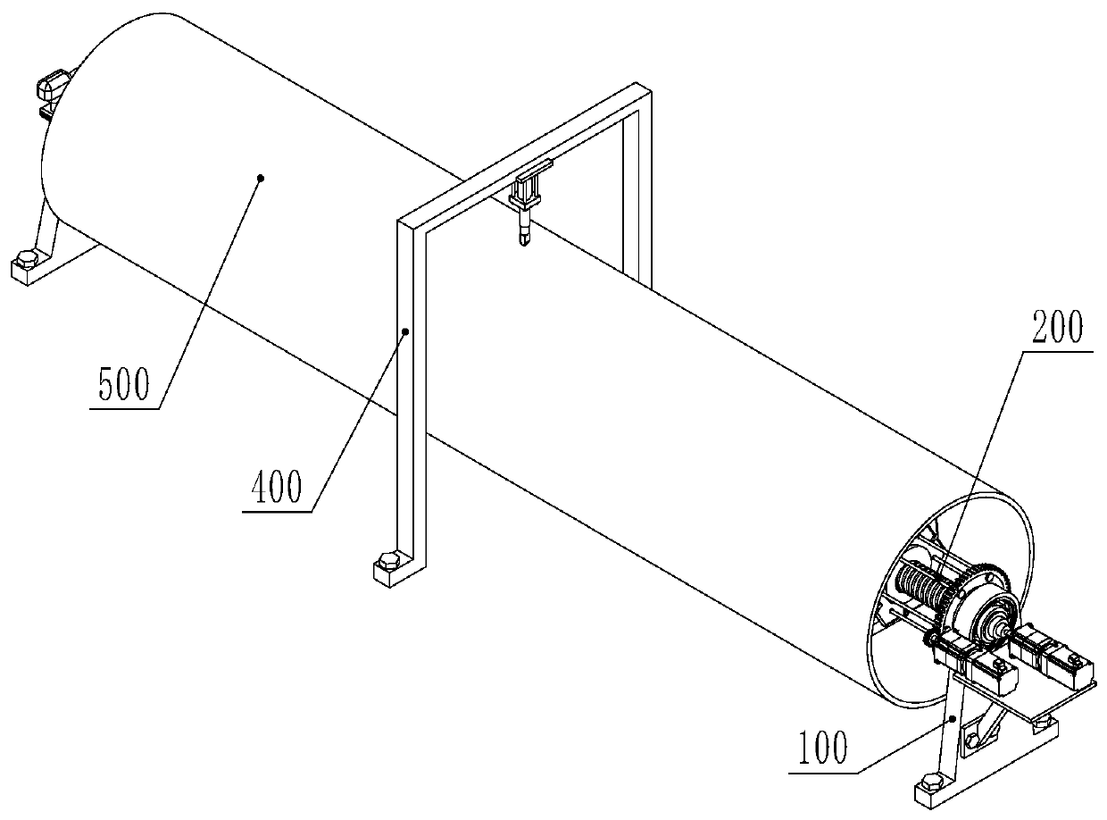
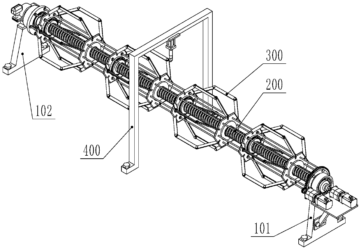
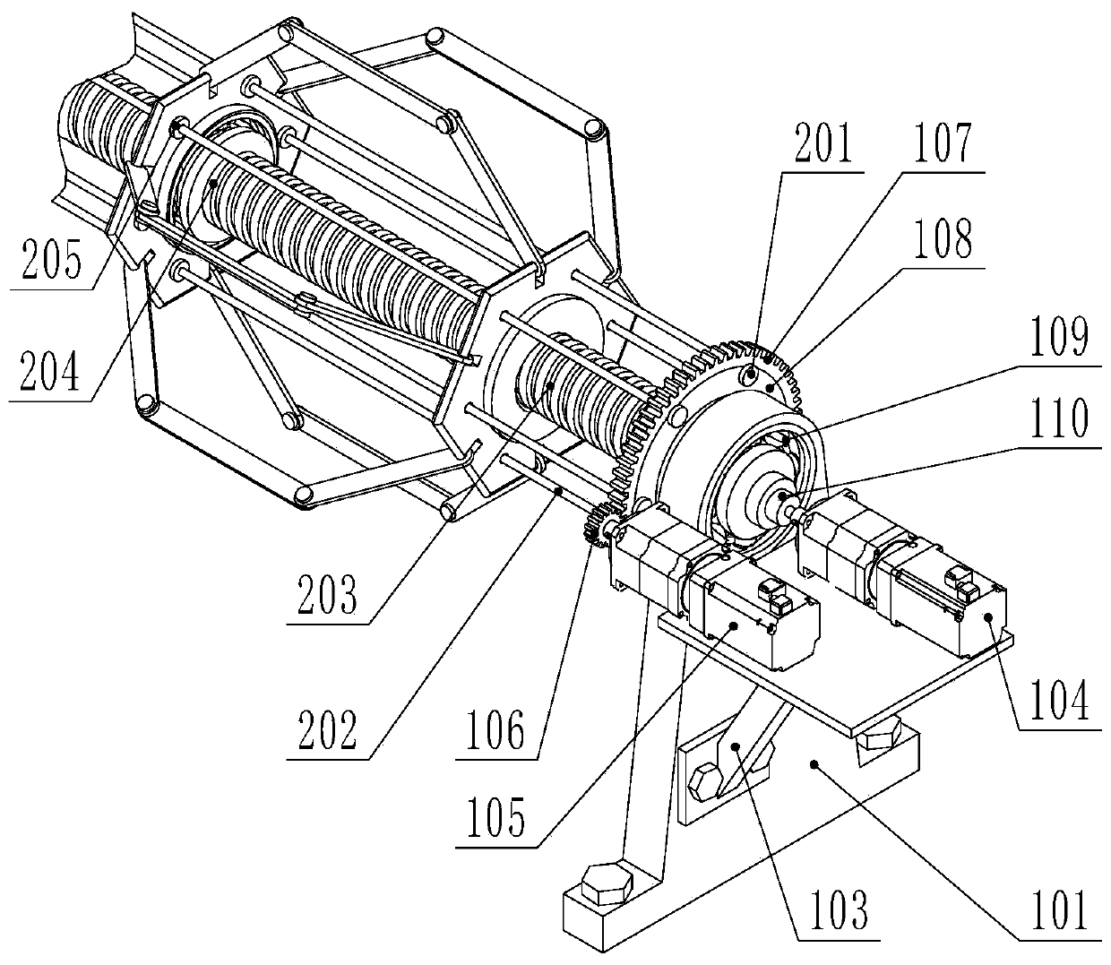
[0033] The present invention is a screw clamping type metal hard tube rotary cutting machine (referred to as cutting machine, see Figure 1-9 ) includes a support device 100, a screw device 200, an expansion device 300 and a cutting device 400. The support device 100 is located at the front and rear ends of the entire cutting machine and is fixed to the ground, which is equivalent to the frame part of the cutting machine; The expansion device 300 is set on the lead screw device 200, and the two devices are connected by threads, and there are four expansion devices 300, which are uniformly arranged before and after, and the metal hard tube 500 to be cut is placed on the expansion device outer cover; the cutting device 400 is located at The screw device 200 is in the middle position, and is also in the middle position in the left-right direction.

[0034] The support d...


PUM


Abstract

The invention provides a lead screw clamping type metal hard tube rotary cutter comprising a supporting device, a lead screw device, at least two expanding devices and a cutting device. The supportingdevice is located at the front and back ends of the whole cutter and fixedly connected with the ground. The front and back ends of the lead screw device are erected on the supporting device and can rotate relative to the supporting device. The expanding devices are both arranged on the lead screw device in a sleeving manner and connected with the lead screw device through threads. The expanding devices are sleeved with a to-be-cut metal hard tube. The cutting device is arranged between the two adjacent expanding devices. The supporting device is provided with an early operation motor and a later operation motor. The two motors can control the lead screw and the expanding devices to rotate correspondingly. The cutter is provided with multiple connection rod structures adopting expanding connection rods and front and back rockers to clamp the metal hard tube, a longer contact area is obtained in the length direction of the metal hard tube, and therefore the lead screw clamping type metal hard tube rotary cutter is suitable for to-be-cut metal hard tubes of different lengths, guarantees reliable clamping and avoids deformation.

Description

technical field [0001] The invention relates to the technical field of metal hard tube cutting machines, in particular to a lead screw clamping type metal hard tube rotary cutting machine. Background technique [0002] With the continuous acceleration of the urbanization process, the people's desire for the construction of rural infrastructure is becoming stronger and stronger. In recent years, drinking water pipelines have been laid on a large scale in many areas, and the demand for cutting water pipelines has surged. The traditional cutting method for metal pipes is cutting with a grinding wheel cutting machine. For example, the patent application number 201711457096.4 provides a steel pipe cutting device, which can realize fast clamping and cutting of steel pipes, but because this device needs to completely penetrate the grinding wheel When the steel pipe is cut, the grinding wheel exerts a great extrusion force on the steel pipe, and it is common for the end of the stee...

Claims


Application Information

Patent Timeline
Patent Type & Authority Applications(China)
IPC IPC(8): B23D79/00
CPCB23D79/00
Inventor 檀润华何川史帆王康刘浩洋
Owner HEBEI UNIV OF TECH
Why Eureka
Try Eureka