Spiral flow constant-pressure pump

A spiral flow constant pressure pump and pump casing technology, which is applied to pumps, parts of pumping devices for elastic fluids, pump components, etc., can solve the problem of low pressure in swirl flow constant pressure pumps, and achieve high outlet pressure Effect

Active Publication Date: 2008-10-29
李世煌
View PDF1 Cites 31 Cited by
  • Summary
  • Abstract
  • Description
  • Claims
  • Application Information

AI Technical Summary

Benefits of technology

The technical effect of this new design for an air conditioner compressor is improved efficiency by creating two types of flows: one from inside the machine's housing towards outside while another swirling around within them. This helps improve cooling performance even further without adding extra parts like fans or duct work.

Problems solved by technology

Inventor describes a new type of fluid pump called Swirl Constant Pressure Pumps (SWCP). These pumps have two main parts: one consisting of a housing for holding liquids or soluble materials; another concave lens inside the housing. One problem addressed by these inventors relates how to increase their performance without increasing power consumption due to the use of multiple components such as motors and gears.

Method used


Image

  • Spiral flow constant-pressure pump
  • Spiral flow constant-pressure pump
  • Spiral flow constant-pressure pump

Examples


Embodiment Construction

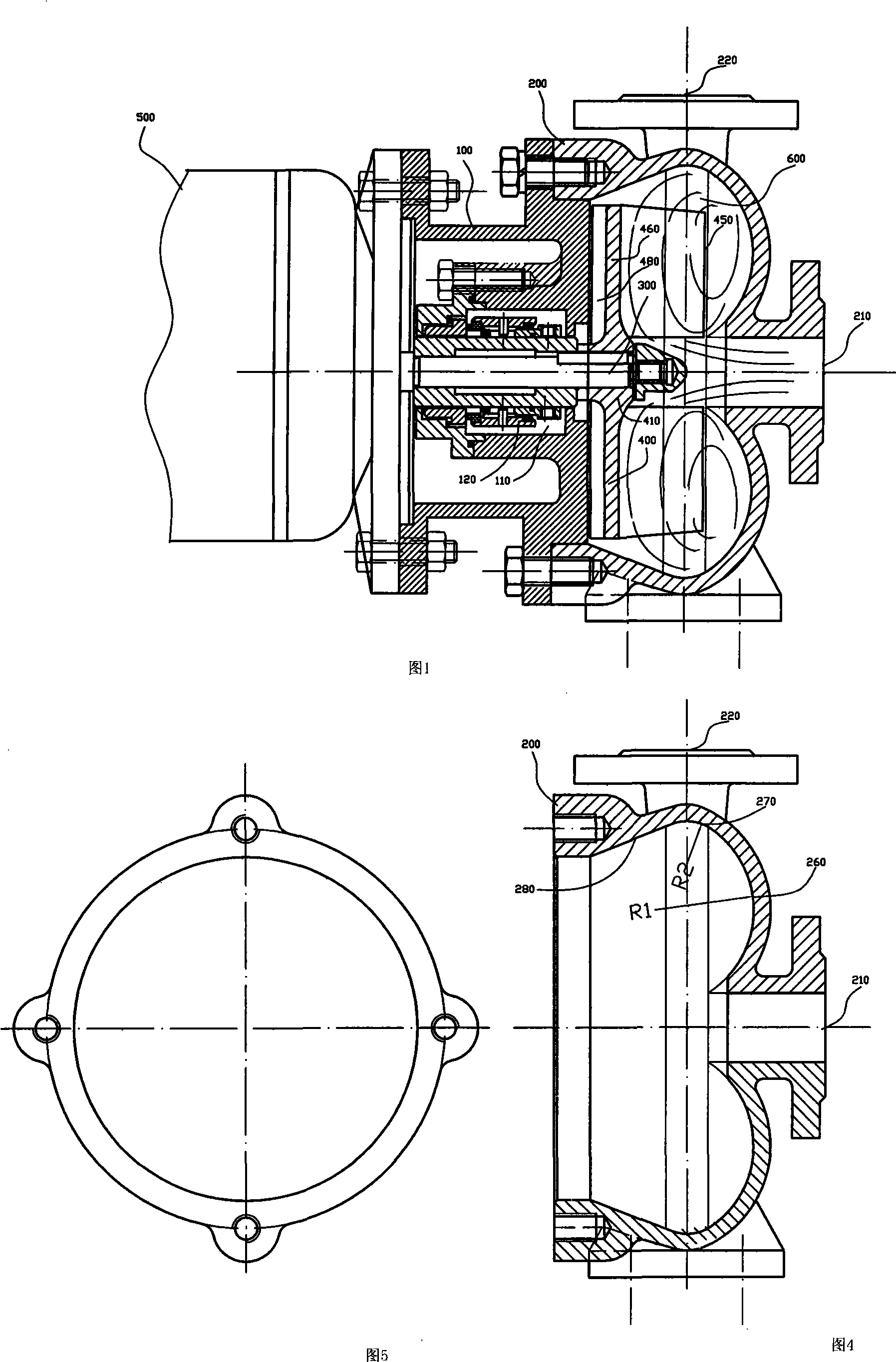
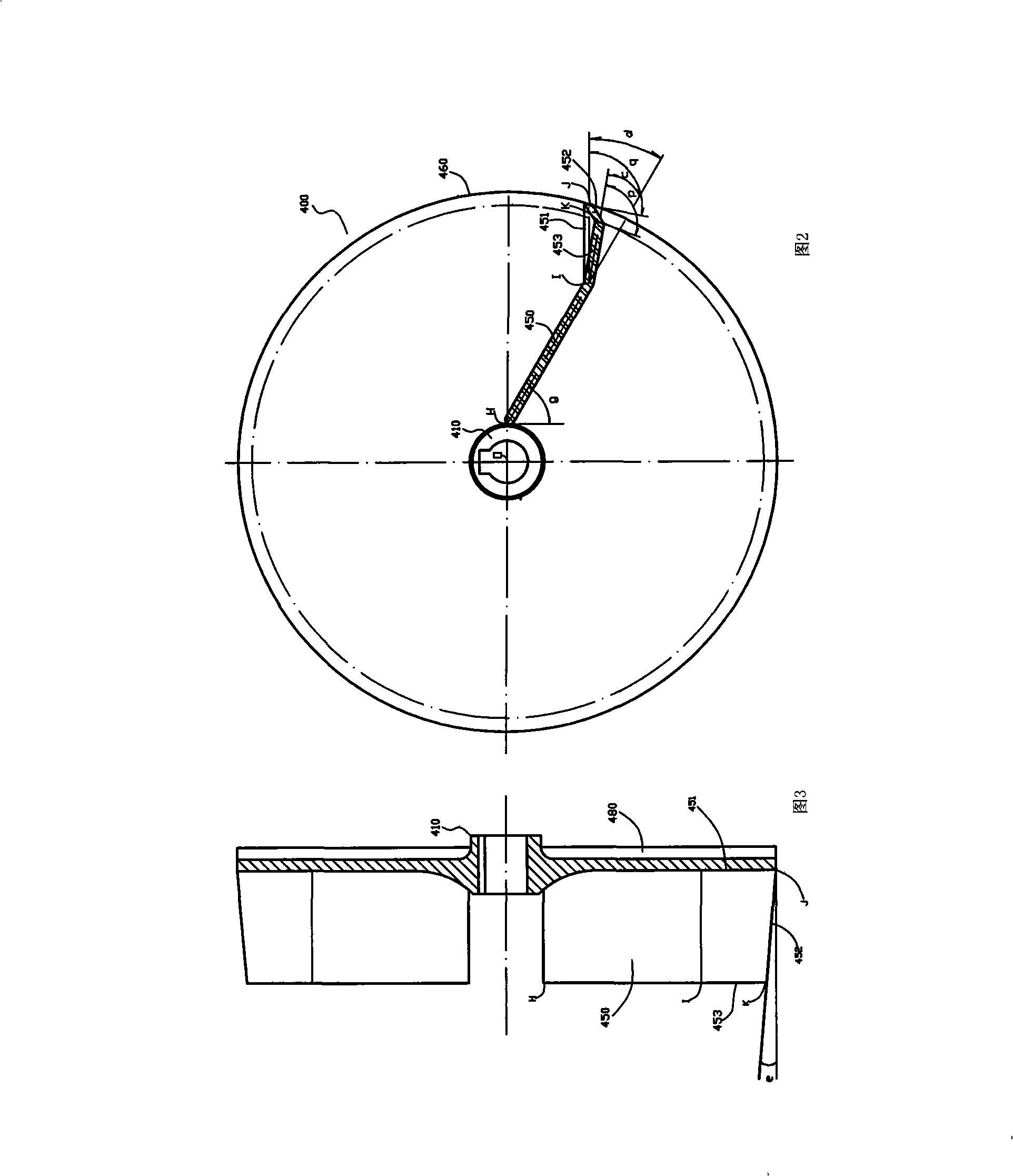
[0024] Referring to FIG. 1 , the spiral flow constant pressure pump of the present invention includes a pump body 100 , a pump casing 200 , a pump shaft 300 , an impeller 400 and a motor 500 .

[0025] The pump casing 200 is fixedly installed on the front side of the pump body 100 , and the pump casing 200 and the pump body 100 jointly form a pump chamber 600 . The motor 500 is fixedly installed on the rear side of the pump body 100 . The shaft of the electric motor 500 serves as the pump shaft 300 . The front end of the pump shaft 300 protrudes into the pump chamber 600 , and the impeller 400 is fixedly installed on the front end of the pump shaft 300 . The pump body 100 has a central sealed cavity 110 . A set of known face seals or mechanical seals 120 is installed in the central seal cavity 110 . The pump housing 200 has a horizontal liquid inlet 210 on the front side and a vertical liquid outlet 220 on the right side. The impeller 400 includes a rear shroud 460 having ...


PUM


Abstract

The invention relates to a centrifugal pump and discloses a spiral flow constant-pressure pump in particular. The spiral flow constant-pressure pump comprises a pump shell and an impeller; wherein, an inner wall of the pump shell is arc-shaped; the impeller comprises a back cover plate and a plurality of front blades, wherein the back cover plate is provided with a hub part, and the front blades are positioned in the front of the back cover plate and formed as a whole with the back cover plate; each front blade bends towards the counter-clockwise direction and inclines towards the clockwise direction in the position close to the circular edge of the back cover plate so as to form a bent and inclined part with a certain included angle with the front surface of the back cover plate. The spiral flow constant-pressure pump of the invention enables liquid in a pump chamber to generate longitudinal flow towards the direction of a pump front cover, and has rotational flow at the same time, thus forming a spiral flow in the pump, so that liquid flow enter the space between the front blades for a plurality of times and the pressure of the space is lifted; compared with the prior spiral flow constant-pressure pump, the pressure of the pump outlet is higher and more stable.

Description


Claims


Application Information

Patent Timeline
Owner 李世煌
Why Eureka
Try Eureka