

Back light module and optical plate
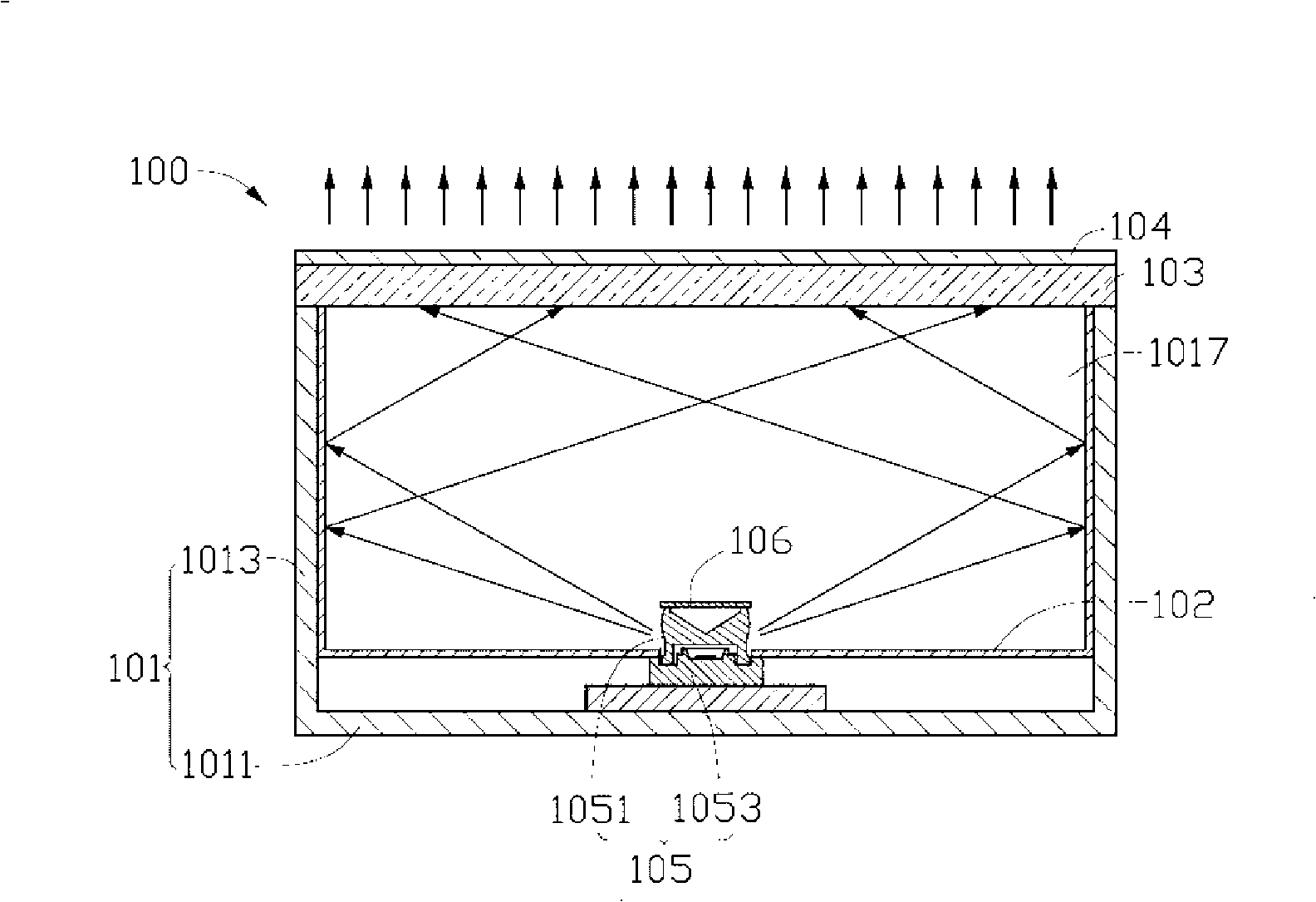
A technology of backlight module and optical plate, applied in optics, optical components, nonlinear optics, etc., can solve the problem of uneven light output of backlight module 100
- Summary
- Abstract
- Description
- Claims
- Application Information
AI Technical Summary
Problems solved by technology
Method used
Image

Examples
Embodiment Construction
[0019] The backlight module and its optical board of the present invention will be further described in detail below with reference to the drawings and embodiments.
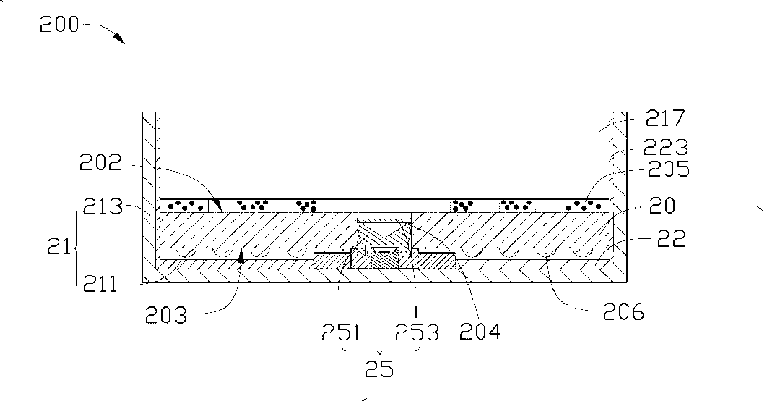
[0020] See figure 2 , shows the backlight module 200 of the preferred embodiment 1 of the present invention, which includes a frame 21 , a reflective plate 22 , an edge-type point light source 25 and an optical plate 20 . The frame 21 includes a rectangular bottom plate 211 and four sidewalls 213 vertically extending from the edge of the bottom plate 211 to the same side thereof and connected to each other. The four side walls 213 and the bottom plate 211 jointly form a cavity 217 for accommodating components such as the side-light point light source 25 , the reflector 22 and the optical plate 20 .
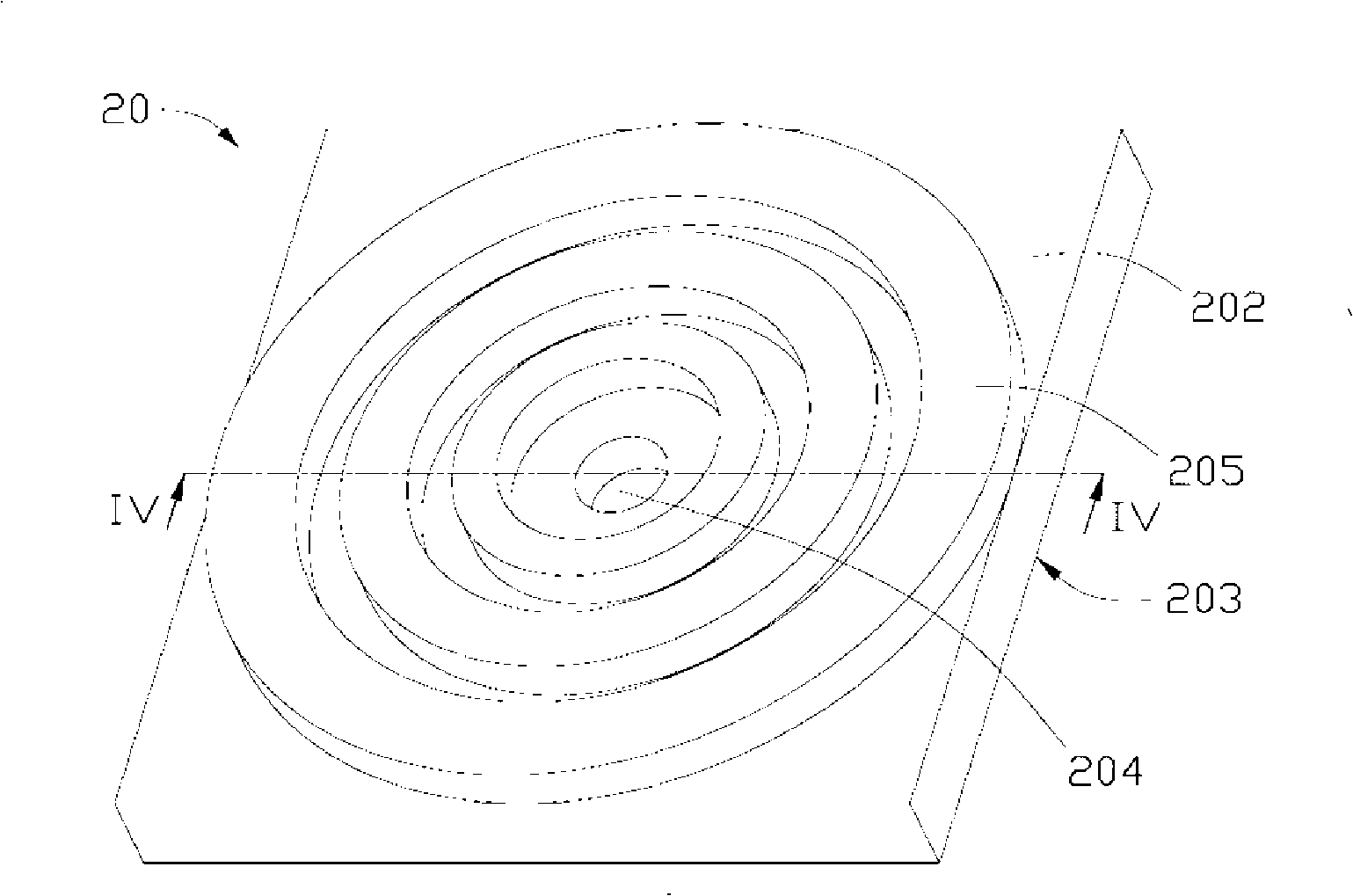
[0021] See also Figure 3 to Figure 5 , the optical plate 20 is rectangular and includes a light-emitting surface 202 and a bottom surface 203 opposite to the light-emitting surface 202 . A light source receiving...
PUM
 Abstract
Description
Claims
Application Information