
Multiple Optical Channel Autocorrelator Based on Optical Circulator

a multi-channel, autocorrelator technology, applied in the direction of measurement devices, instruments, optics, etc., can solve the problems of large loss of optical signals in the optical path of long-distance space, interference between two signals, and limited gauge of sensing fibers, so as to improve the multiplexing capability of the sensing system, improve the stability and reliability of the measurement system, and improve the effect of effective utilization of the output power of the light sour

Inactive Publication Date: 2016-06-30
HARBIN ENG UNIV
View PDF11 Cites 2 Cited by
  • Summary
  • Abstract
  • Description
  • Claims
  • Application Information

AI Technical Summary

Benefits of technology

[0010]The purpose of the present invention is to provide a multiple optical channel autocorrelator based on an optical fiber circulator for sensing, which can achieve in line real time monitor and measurement for physical amount, such as multiple points strain or deformation, solve many problems as that power attenuation of light source is big, efficiency is low, the precision in measurement is degraded which is caused by the feedback light of the light source appeared in the optical path, etc, when many sensors are multiplexed in one optical fiber, and improve the stability of the system.
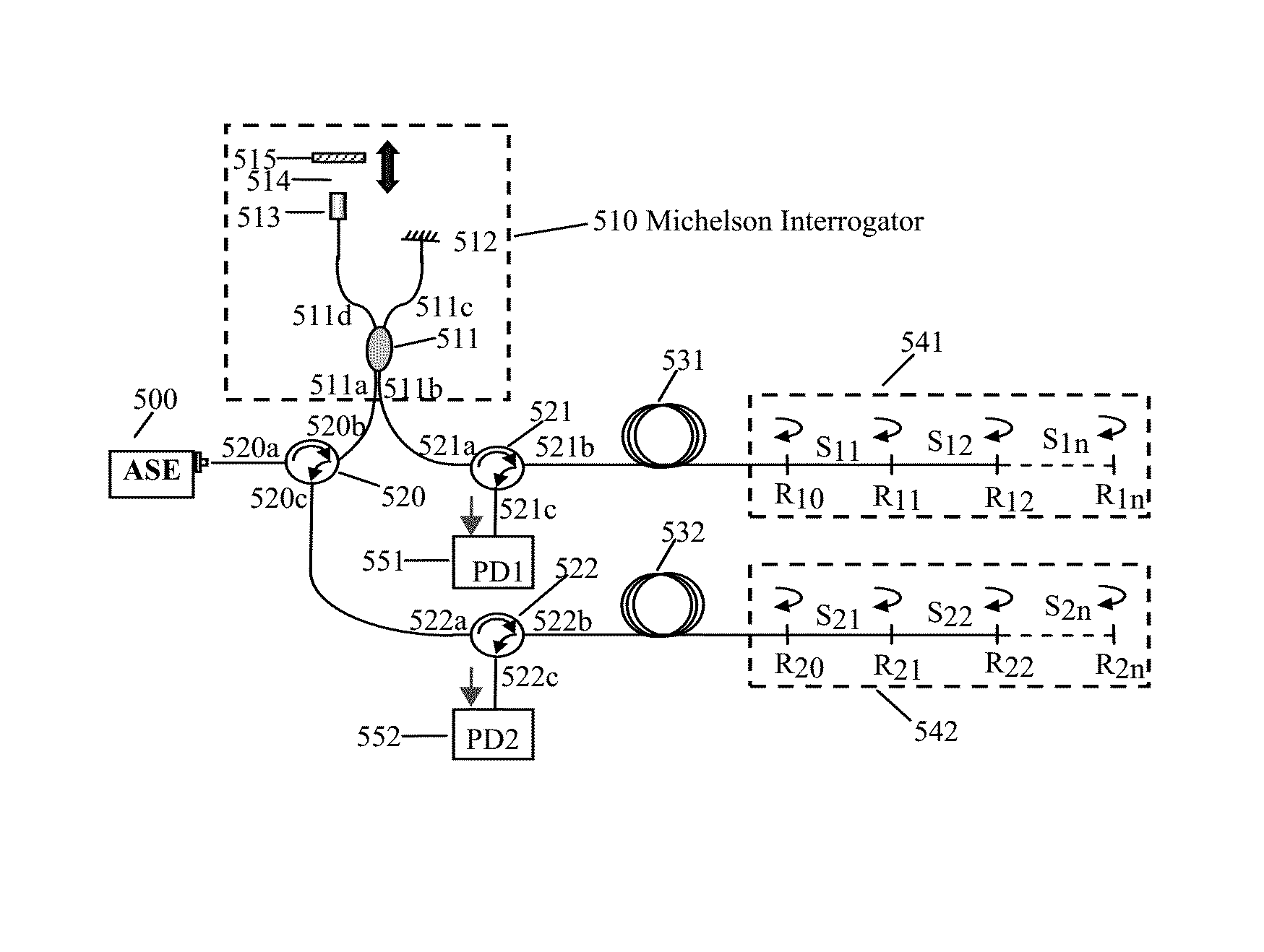
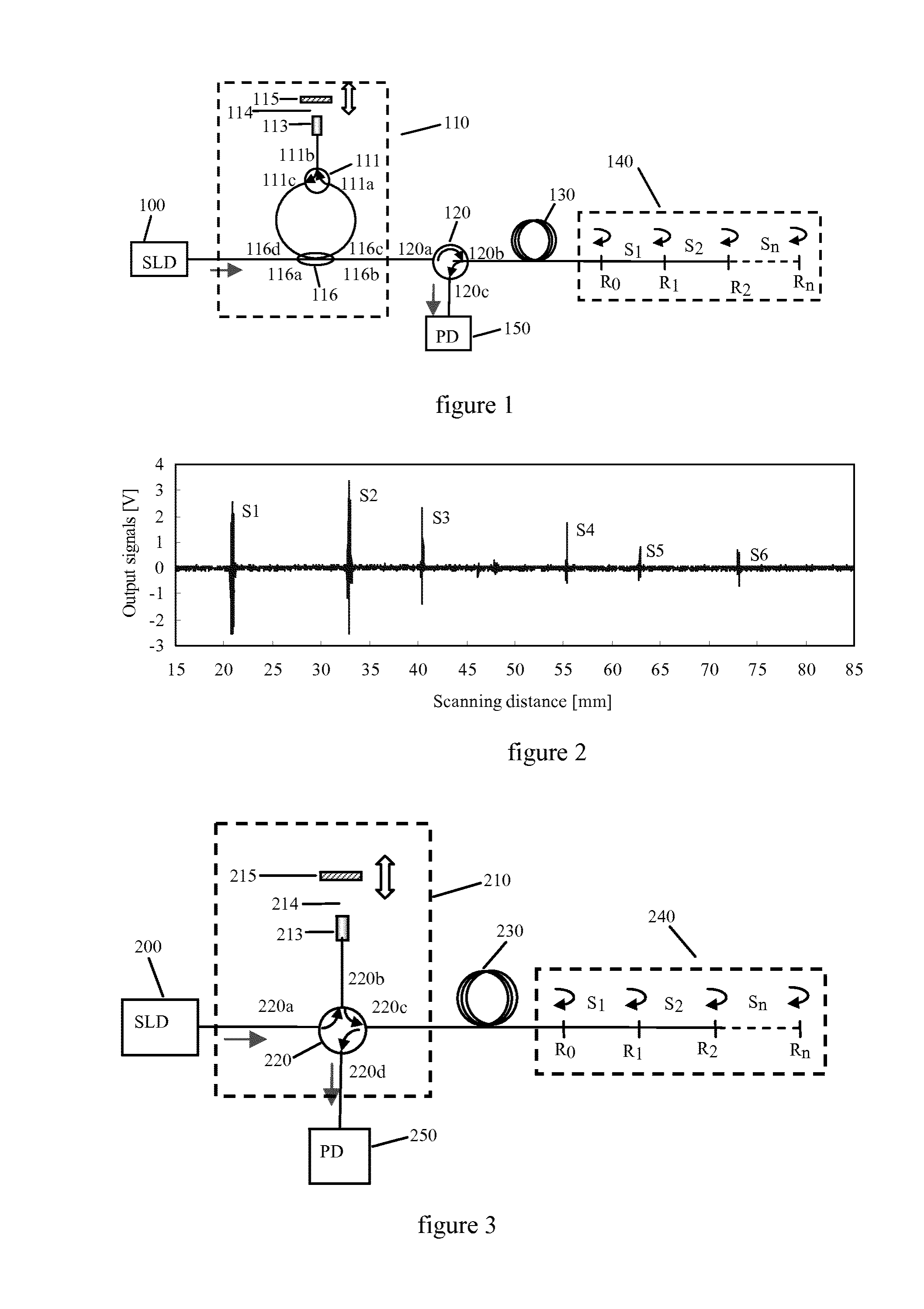
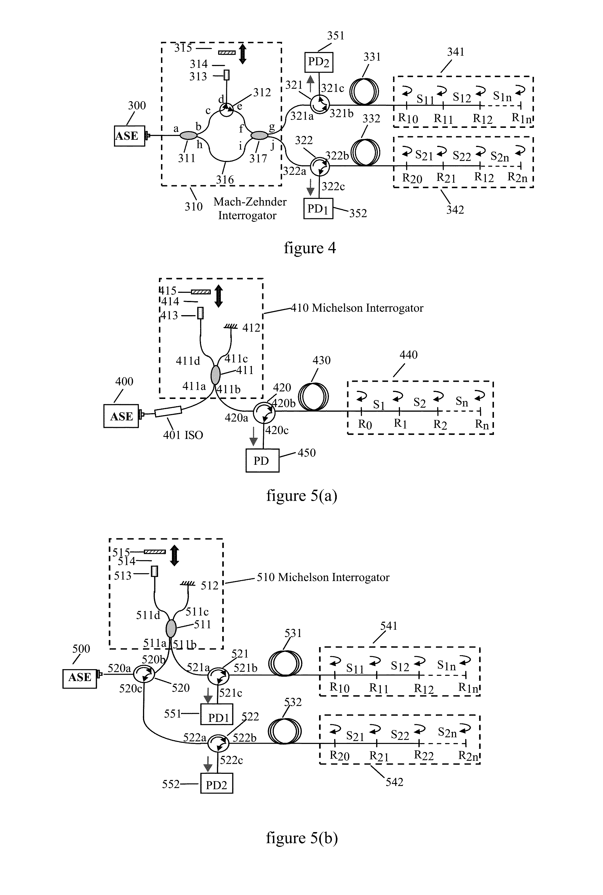
[0018]The basic components of the present invention includes: a broad-band light source, such as a Light-Emitting Diode (LED), a Super-Luminescent Diode (SLD) or an Amplified Spontaneous Emission light source (ASE); an adjustable multiple light beams generator, which includes a position-adjustable scanning mirror to generate an adjustable delay matched with the gauge of each sensor between the reference signal and sensing signal; one or more optical fiber circulators, which is used to improve the effective utilization of the optical power of the light source output, thereby improving the multiplexing capability of the sensing system; input / output optical fiber, whose length can be up to several kilometers or even longer, in order to achieve remote measurement; one or more fiber optic sensor arrays, composed of optical fibers with several fragments of well cut end faces and a certain reflectance, connected end to end, one partial mirror is formed at the connecting end face between two fragments of adjacent optical fibers; one or more photoelectric detectors for detecting interference signal.
[0021]1, by introducing optical fiber circulator, the effective utilization of the output power of the light source is improved, thereby improving the multiplexing capability of the sensing system.
[0022]2, by constructing an optical path structure of unidirectional transmission, it avoids the light beam fed back to the light source, to improve the stability and reliability of the measurement system.
[0023]3, by constructing a structure of entirely shared optical path, it achieves the match of entirely shared optical path of multi-scale quasi-distribution, reducing the impact brought by the optical path for the system detection.
[0024]The present invention can achieve in line real time monitor and measurement for physical amount, such as multiple points strain or deformation, solve many problems as that power attenuation of light source is big, efficiency is low, the precision in measurement is degraded which is caused by the feedback light of the light source appeared in the optical path, etc., when many sensors are multiplexed in one optical fiber, and improve the stability of the system. Using the optical path difference adjustable double-beam or multi-beam generator, it can generate two-beam or multi-beam optical path difference adjustable query beam under the help of the introduced optical path delay between the reference optical path and the sensing optical path. When the optical path difference of these different query beams is equal to the optical path between two end faces of the front and rear in some optical fiber sensor, the interference of low-coherence light can be achieved, and it can be further used to construct an optical fiber sensor array, or a distributed white light interferometer strain sensing system over the network.

Problems solved by technology

If optical path difference between the sensing arm and the reference arm is less than a coherence length of the light source, interference occurs between two signals.
However, for the structure of the conventional optical fiber white light interferometer, the gauge of the sensing fiber is limited by the adjustable distance range in the reference arm.
Further, even if the long distance adjustable range can be obtained, the transmission loss of the optical signal in the optical path of the long-distance space will be huge.
In the sensor array, each sensor is connected end to end, part mirrors are formed by the connecting end faces of the adjacent sensors, which causes an interference between the reflected signals of the adjacent mirrors.
However, in the above described multiplexed interferometer based on space division multiplexing, the power attenuation of light source is high, the light source utility rate is low, only a small part of the light emitted from light source arrive the sensor array, which is received by the detector and formed an interference pattern.

Method used


Image

  • Multiple Optical Channel Autocorrelator Based on Optical Circulator
  • Multiple Optical Channel Autocorrelator Based on Optical Circulator
  • Multiple Optical Channel Autocorrelator Based on Optical Circulator

Examples


Embodiment Construction

[0030]Hereinafter, the present invention will be described in details by referring to examples of the accompanying drawings.

[0031]The detailed embodiment of the invention is based on an optical fiber circulator, which is used for distributed real time monitor and measurement for material and geometric features of the building structure, and includes one double or multiple light beams generator, and at least an optical fiber sensor array. The multiple light beams generator is used to generate sensing signal with fixed optical path and reference signal with adjustable delay line. The multiple light beams generator may has a different structure, but it at least should include an optical path fixed arm and an optical path adjustable arm, the optical path adjustable arm is composed of a Grads Refraction rate (GRIN) lens connected to the end of the optical fiber and a scanning mirror installed on a linearity shift platform. The scanning mirror is used to adjust the optical path difference...


PUM


Abstract

A multiple optical channel autocorrelator based on an optical fiber circulator includes a broad-band light source, at least an optical-fiber sensor array, an adjustable multiple light beams generator, at least an optical fiber circulator and at least a photoelectric detector. The optical-fiber sensor array is composed of the sensing fibers connected end to end. The in line mirrors are formed by the connecting end faces of the adjacent fibers. The adjustable multiple light beams generator includes a fixed arm and an adjustable arm. The optical path difference between the fixed arm and the adjustable arm is adjustable in order to match the optical path of each sensor in the sensor array. The optical fiber circulator couples the signals generated by the multiple light beams generator to the sensor array, and couples the signals returned by the sensor array to the photoelectric detector. The photoelectric detector is connected to the optical fiber circulator. The multiple optical channel autocorrelator based on the optical fiber circulator can implement the real-time in line measurement of the physical quantity of multipoint strain or deformation, and has advantages of low light source power loss, high efficiency and good stability.

Description

CROSS-REFERENCE TO RELATED PATENT APPLICATIONS[0001]This application is a Divisional of U.S. application Ser. No. 13 / 877,772 (National Stage of PCT / CN2010 / 001563), filed Apr. 4, 2013, incorporated herein by reference in its entirety.TECHNICAL FIELD[0002]The present invention relates to an autocorrelator for sensing and, more particularly relates to a distributed measurement device capable of causing changes of the absolute optical path by stress, strain and temperature, etc.BACKGROUND ART[0003]An interferometer which uses a broad-band light as a light source and a fiber as a transmission medium is white-light optical fiber interferometer. The traditional optical fiber white-light interferometer usually includes a sensing arm and an adjustable reference arm, and signals transmitted along the sensing arm and the reference arm are detected by a photodetector. If optical path difference between the sensing arm and the reference arm is less than a coherence length of the light source, in...

Claims


Application Information

Patent Timeline
Patent Type & Authority Applications(United States)
IPC IPC(8): G01B9/02G02B6/293
CPCG01B9/02015G02B6/29349G02B6/2932G01B11/161
Inventor YUAN, LIBOYANG, JUNZHOU, AI
Owner HARBIN ENG UNIV
Learn More