Virtual reality display device

A display device and virtual reality technology, applied to optics, instruments, electrical components, etc., can solve the problems of not being able to enter the optical system and low optical utilization rate, and achieve the effect of improving display brightness and improving optical utilization rate

Inactive Publication Date: 2019-08-23
SEEYA OPTRONICS LTD
View PDF8 Cites 2 Cited by
  • Summary
  • Abstract
  • Description
  • Claims
  • Application Information

AI Technical Summary

Problems solved by technology

exist figure 1 In the shown structure, when the light R1 emitted by the display device 14 passes through the first linear polarizer 16, part of the light is lost, and this part of the light is perpendicular to the transmission axis of the first linear polarizer 16 because the vibration direction is perpendicular to the transmission axis of the first linear polarizer 16. Absorption, cannot enter the subsequent optical system, resulting in low optical utilization

Method used


Image

  • Virtual reality display device
  • Virtual reality display device
  • Virtual reality display device

Examples


Embodiment 1

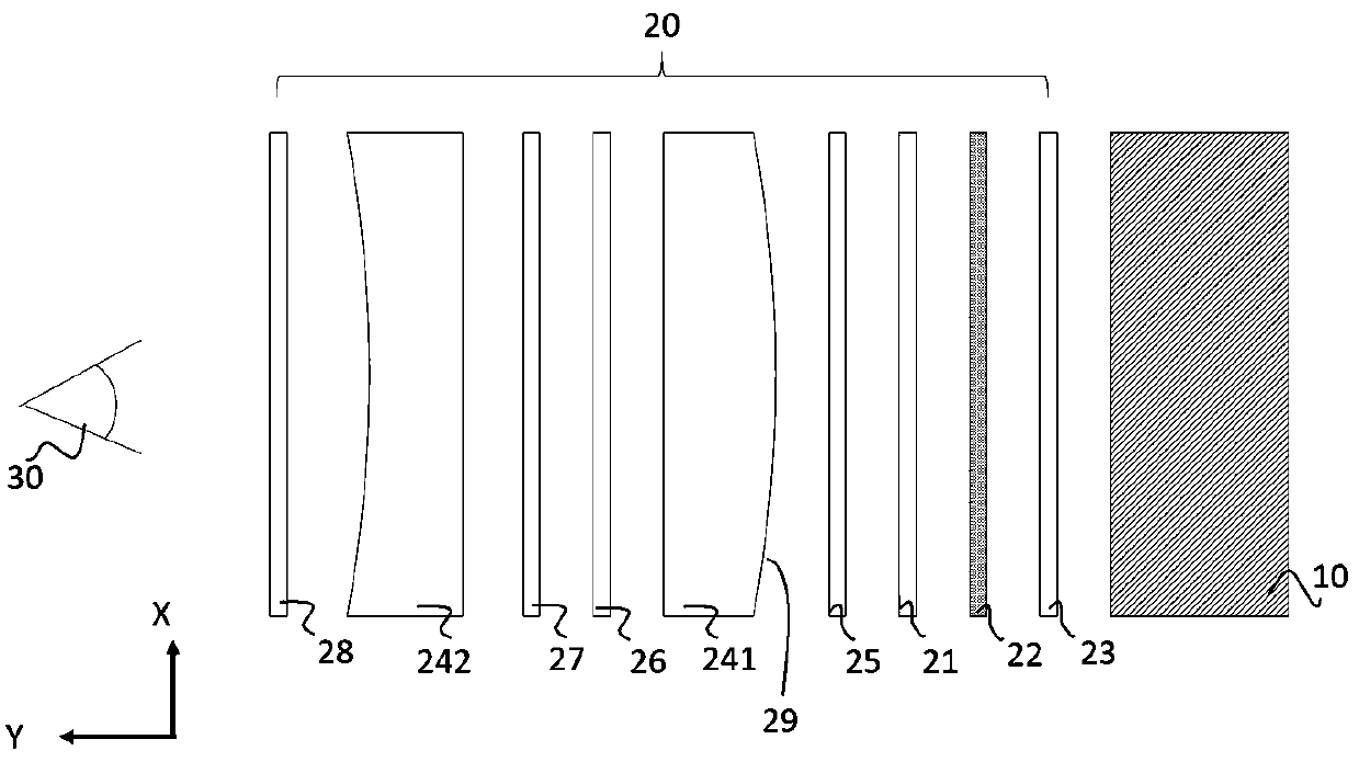
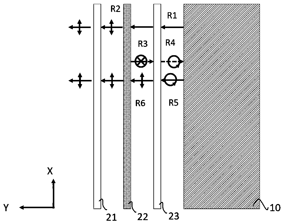
[0034] figure 2 A schematic diagram of a virtual reality display device provided for Embodiment 1 of the present invention, as shown in the figure, the virtual reality display device includes an OLED (Organic Light-Emitting Diode, Organic Light-Emitting Diode) display panel 10 and an optical system 20, and the optical system 20 is set Between the OLED display panel 10 and the user viewing side 30 . The OLED display panel 10 is used to generate images. The light emitted by the OLED display panel 10 is different from the light emitted by the liquid crystal display device. The light emitted by the liquid crystal display device is polarized light, while the light emitted by the OLED display panel is close to natural light. The optical system 20 is used to pull the near image generated by the OLED display panel 10 to a far distance and magnify it, so as to almost fill the field of vision of a person, thereby creating a sense of immersion. The optical system 20 is a polarization c...

Embodiment 2

[0045] Figure 7 A schematic diagram of a virtual reality display device provided in Embodiment 2 of the present invention, as shown in the figure, the virtual reality display device includes an OLED display panel 40 and an optical system 50, and the optical system 50 is arranged between the OLED display panel 40 and the user observation side 30 . The OLED display panel 40 is used to generate images, and the light emitted by the OLED display panel 40 is close to natural light. The optical system 50 is used to pull the near image generated by the OLED display panel 40 to a far distance and magnify it, so as to almost fill the field of vision of a person, thereby creating a sense of immersion. The optical system 50 is a polarization catadioptric optical system, which needs to polarize the natural light generated by the OLED display panel 40 first, and then perform subsequent processing. The optical system 50 includes a first linear polarizer 51 arranged between the OLED displa...


PUM


Abstract

The invention provides a virtual reality display device. The device includes an OLED display panel and an optical system. The optical system is arranged between the OLED display panel and a user observation side. The optical system includes a first linear polarizer arranged between the OLED display panel and the user observation side, a first reflective and transmissive optical film arranged between the first linear polarizer and the OLED display panel and a first 1/4 wave plate arranged between the first reflective and transmissive optical film and the OLED display panel. According to the invention, through the arrangement of the first reflective and transmissive optical film and the first 1/4 wave plate, linear polarized light which cannot pass through the first liner polarizer is converted into linear polarized light which can pass through the first liner polarizer to enter the subsequent optical system, which improves the optical utilization of the virtual reality display device and improves the display brightness of the virtual reality display device.

Description

technical field [0001] The invention relates to the field of display technology, in particular to a virtual reality display device. Background technique [0002] VR (Virtual Reality, virtual reality) display was proposed by Jaron Lanier, the founder of the American VPL company in the 1980s. It integrates computer graphics technology, computer simulation technology, sensor technology, display technology and other science and technology. Creating a virtual information environment on the information space can enable users to have an immersive sense of immersion, have a perfect interaction ability with the environment, and help to inspire ideas. [0003] A virtual reality display device in the prior art generally includes a computer processing system, an image processing system, a display panel, and an optical system. Among them, the computer processing system captures the character's behavior and the external environment through external sensors, and then processes according t...

Claims


Application Information

Patent Timeline
Patent Type & Authority Applications(China)
IPC IPC(8): G02B27/01
CPCG02B27/0101G02B27/0172G02B27/283H10K50/856H10K50/868H10K50/858
Inventor 牛磊刘波
Owner SEEYA OPTRONICS LTD
Why Eureka
Try Eureka