
Light source carrier board and side light source

A side-entry, carrier board technology, applied in optics, nonlinear optics, lighting devices, etc., can solve problems such as scratches on optical films, lower optical utilization efficiency, and component damage, so as to avoid damage and improve optical utilization Effect

Active Publication Date: 2008-03-19
AU OPTRONICS CORP
View PDF0 Cites 2 Cited by
  • Summary
  • Abstract
  • Description
  • Claims
  • Application Information

AI Technical Summary

Problems solved by technology

However, in the process of assembling or replacing the light source, when the backlight module is placed sideways, if it is too close to the optical film, it will easily cause damage to the components or scratches on the optical film; if it is not close to or even far away from the optical film, However, it will reduce the optical utilization efficiency

Method used


Image

  • Light source carrier board and side light source
  • Light source carrier board and side light source
  • Light source carrier board and side light source

Examples


Embodiment Construction

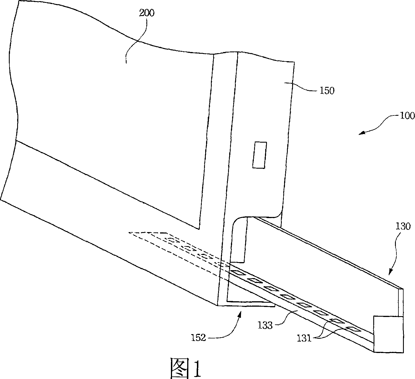
[0027] 1, which shows a three-dimensional schematic diagram of the side-lit light source structure of the present invention. The edge light source structure 100 mainly includes a light source carrier structure 130 and a plastic frame 150. The light source carrier board structure 130 includes a plurality of point light sources 131 disposed on the carrier board 133. The side corner of the plastic frame 150 has an opening 152 for the light source carrier structure 130 to be inserted therein. The optical film 200 may be a light guide plate, a reflection sheet, a light collection sheet, a diffusion sheet, or a combination thereof. The edge light source structure 100 provides a uniform backlight through the optical film 200.

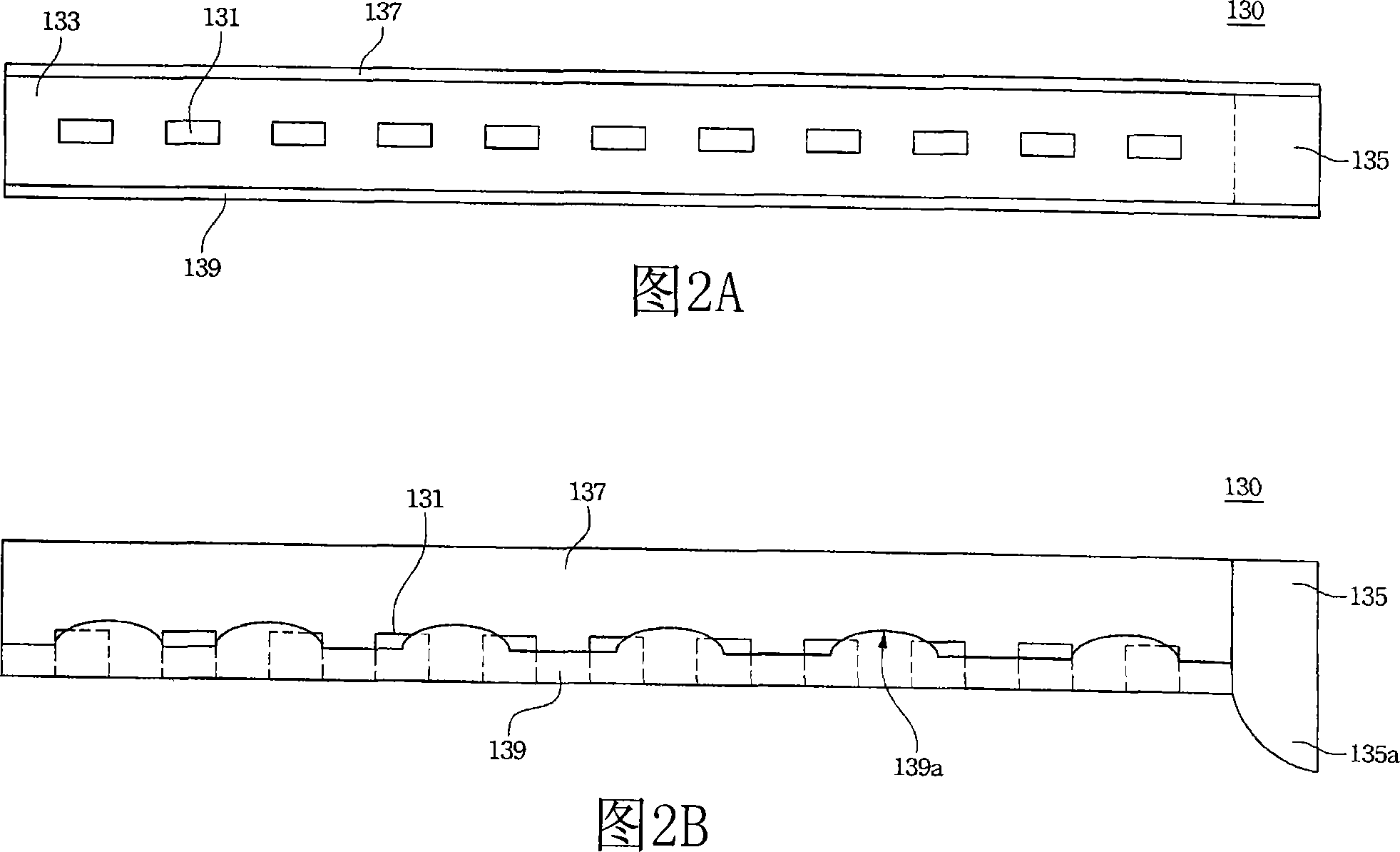
[0028] Refer to FIG. 2A and FIG. 2B together. 2A is a top view of the light source carrier structure of the present invention, and FIG. 2B is a side view thereof. The light source carrier board structure 130 has a plurality of point light sources 131 disposed on t...


PUM


Abstract

The present invention discloses a light source carrier board structure, which includes a carrier board, a plurality of point light sources, a first side board, and a plurality of flanges. The point light sources are arranged on the carrier board. The first side board is essentially perpendicular to the carrier board, and arranged on a long side of the carrier board. The flanges are arranged on the first side board, and the extension direction of the flanges is essentially perpendicular to the carrier board. When the flanges of the side board with the light source carrier board structure is used to avoid the light source configure, the point light source contacts with the optical film piece directly. Hereon, the present invention also discloses a side entry type light source structure. The light source carrier board structure and the side entry type light source structure of the present invention can prevent the components or the optical film piece from being damaged, and can improve the optical utilization rate.

Description

Technical field [0001] The present invention relates to a structure of a backlight module, and in particular to a structure of a backlight module with an edge light source. Background technique [0002] Liquid crystal displays have the advantages of low power consumption, light weight and thin thickness, so they are widely used in various electronic products. However, the liquid crystal itself does not emit light, and the liquid crystal display needs to display images through external light sources, so the backlight module is an indispensable part of the liquid crystal display. [0003] The light source of the backlight module mainly includes cold cathode fluorescent lamp (CCFL) and light emitting diode (LED). Light-emitting diodes have the characteristics of high brightness, high color purity, long life, no mercury, and good reliability. The backlight module structure can be divided into two types: bottom lighting and edge lighting. [0004] Generally speaking, the direct type s...

Claims


Application Information

Patent Timeline
IPC IPC(8): G02F1/13357F21V21/00G02F1/1335
Inventor 许清锋
Owner AU OPTRONICS CORP
Learn More