Light guide plate die, light guide plate and manufacturing method of light guide plate

A light guide plate and mold technology, applied in optics, light guides, household appliances, etc., can solve the problem of small effective optical utilization area, achieve the effect of increasing effective optical utilization area, increasing surface area, and increasing optical utilization rate

Pending Publication Date: 2017-08-25
SHANXI YUHAO NEW OPTICAL MATERIALS CO LTD
View PDF0 Cites 2 Cited by
  • Summary
  • Abstract
  • Description
  • Claims
  • Application Information

AI Technical Summary

Problems solved by technology

After practice, the light guide point is a fully convex lig

Method used


Image

  • Light guide plate die, light guide plate and manufacturing method of light guide plate
  • Light guide plate die, light guide plate and manufacturing method of light guide plate
  • Light guide plate die, light guide plate and manufacturing method of light guide plate

Examples


Embodiment 1

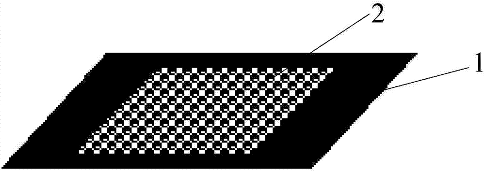
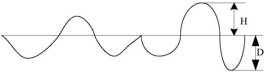
[0028] This embodiment provides a light guide plate mold, such as figure 1 As shown, the light guide plate mold includes a mold body 1 and several shaped light guide point structures 2 arranged on the mold body. The shaped light guide point structures 2 are concave-convex. Wherein, the shape of the light guide point stereotyped structure 2 is as follows: figure 2 shown.

[0029] By setting the shape of the light guide point shaping structure 2 to be concave-convex-convex-convex-concave, the shape of the light guide point on the light guide plate prepared based on the light guide plate mold is convex-convex-convex-concave-convex, that is, the shape of the light guide point is concave and convex. , compared with the light guide point that only includes the convex part, since the present invention adopts a multi-level convex-concave structure on a tiny light guide point of the light guide plate, the surface structure can be continuously changed and the surface area of ​​the int...

Embodiment 2

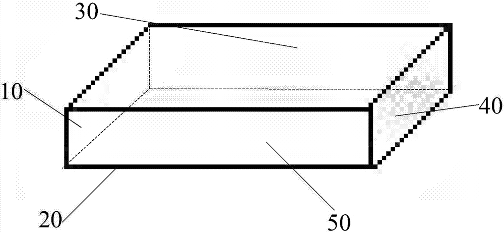
[0034] This embodiment provides a light guide plate, including a plate body, such as image 3 As shown, the plate body includes a light incident surface 10 ( image 3 The left side of the middle), a reflective surface 20 intersecting the incident surface 10 ( image 3 The bottom surface in), a light-emitting surface 30 ( image 3 The top surface in), a reflective light incident surface 40 set opposite the light incident surface 10 ( image 3 The right side of the middle) and the two opposite sides 50 ( image 3 In the front and back), the light incident surface 10 is set facing the light source, and several light guide points are set on the reflective surface 20 . Such as Figure 4 or as Figure 5 As shown, the shape of the light guide point is convex and concave. Wherein, the light guide point can be prepared based on the light guide plate mold in the above-mentioned embodiment 1.

[0035] In this embodiment, by setting the shape of the light guide point as a convex-co...

Embodiment 3

[0042] This embodiment provides a method for preparing a light guide plate, including the following steps:

[0043] Step 1, using a laser to etch a plurality of concave-convex shaped light guide point stereotyped structures on the mold body to obtain a concave-convex light guide plate mold.

[0044] Wherein, the relevant content of the shaped structure of the light guide point has been explained in detail in the above-mentioned embodiment 1, for details, please refer to the content in the above-mentioned embodiment 1, which will not be repeated here.

[0045]Step 2, paste the light guide plate mold on a roller of the roll-to-roll heat press, place the light guide plate between the two rollers of the roll-to-roll heat press, and heat the roll-to-roll heat press Apply pressure to transfer the shaped structure of several light guide points on the light guide plate mold to the reflective surface of the light guide plate to obtain a light guide plate including several light guide p...


PUM


Abstract

The invention provides a light guide plate mold, a light guide plate and a preparation method thereof, belonging to the display field. The mold for the light guide plate includes a mold body and several shaped structures of light guide points arranged on the mold body. The light guide plate includes a plate body, and the plate body includes a light incident surface, a reflective surface intersecting the light incident surface, a light exit surface opposite to the reflective surface, and a light exit surface opposite to the light incident surface. The light-incident surface and the two opposite side faces, the light-incident surface is set facing the light source, and several light guide points are arranged on the reflective surface, and the shape of the light guide points is concave-convex-convex-concave-convex. In the present invention, the shaped structure of the light guide point is set to be concave-convex-convex-convex-convex, so that the shape of the light guide point on the light guide plate prepared based on the light guide plate mold is concave-convex-convex-concave-convex, that is, the shape of the light guide point is concave and convex. , compared with the light guide point including only the convex part, the optically effective utilization area can be enlarged.

Description

technical field [0001] The invention relates to the field of display technology, in particular to a mold for a light guide plate, a light guide plate and a preparation method thereof. Background technique [0002] The light guide plate is obtained by preparing the upper light guide point on the bottom surface (reflective surface) of the acrylic / PC plate with a material with extremely high reflectivity and no light absorption. When the light hits each light guide point on the light guide plate, the reflected light will spread to all angles to destroy the total reflection conduction of the plane. Through light guide points of various densities and sizes, the light guide plate can be made to emit light evenly. The shape and size of the light guide point on the light guide plate will affect the size of the optically effective utilization area of ​​the display device. [0003] At present, when preparing light guide points on a light guide plate, a light guide plate mold with co...

Claims


Application Information

Patent Timeline
IPC IPC(8): B29C59/04B29C33/42G02B6/00B29L11/00B29L7/00
CPCB29C59/04B29C33/42B29L2007/002B29L2011/0075G02B6/0036G02B6/0065
Inventor 王冬明林义芳冀国彪
Owner SHANXI YUHAO NEW OPTICAL MATERIALS CO LTD
Why Eureka
Try Eureka