Projection display system based on full-color light-emitting diode matrixes

A light-emitting diode and projection display technology, applied in optics, instruments, projection devices, etc., to achieve the effect of reducing power consumption and improving optical utilization

Inactive Publication Date: 2014-12-03
INST OF SEMICONDUCTORS - CHINESE ACAD OF SCI
View PDF5 Cites 1 Cited by
  • Summary
  • Abstract
  • Description
  • Claims
  • Application Information

AI Technical Summary

Problems solved by technology

But the system is only suitable for lighting or decorative environment

Method used


Image

  • Projection display system based on full-color light-emitting diode matrixes

Examples


Embodiment Construction

[0022] In order to make the object, technical solution and advantages of the present invention clearer, the present invention will be further described in detail below in conjunction with specific embodiments and with reference to the accompanying drawings.

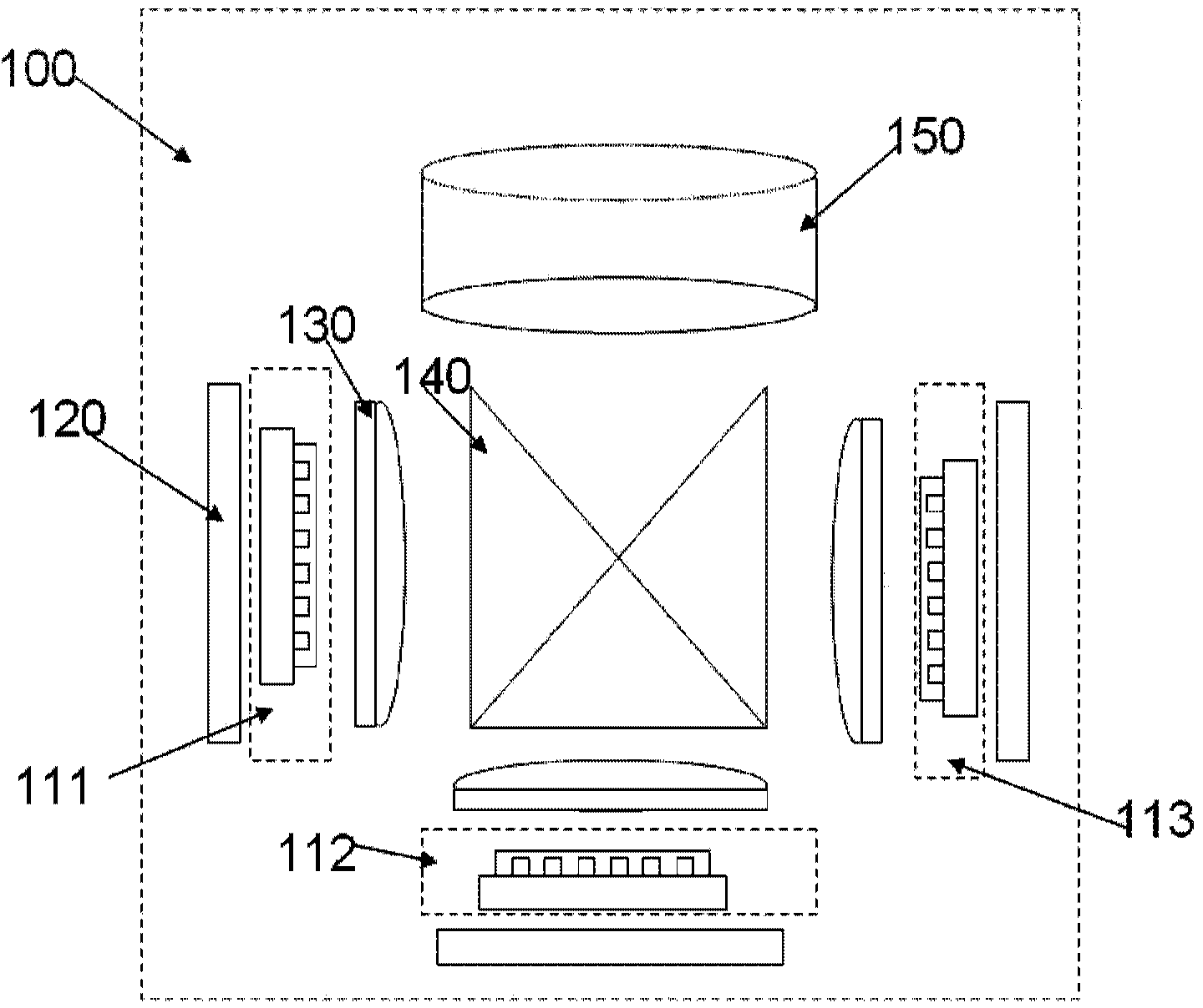
[0023] see figure 1 The schematic diagram of the structure of the embodiment, the projection display system 100 based on the full-color light-emitting diode array provided by the present invention includes:

[0024] Three groups of LED array modules:

[0025] It consists of three LED display arrays 111, 112, 113 with different wavelengths. The manufacturing method is to fix a plurality of LED light-emitting chips in an array on a substrate with wiring, and then use packaging materials to package the array of light-emitting chips on the substrate. In the packaging process, an optional step of coating phosphor is added; wherein, each of the light-emitting diode arrays is composed of a plurality of identical LED chips;

...


PUM


Abstract

The invention discloses a projection display system based on full-color light-emitting diode matrixes. The projection display system comprises three light-emitting diode matrix modules, heat dissipation elements, light collection elements, a light mixing element and a projection element. The light-emitting diode matrix modules comprise the three light-emitting diode display matrixes with different wave lengths. The heat dissipation elements serve as accessories of the three light-emitting diode matrixes and are used for dissipating heat. The light collection elements are placed in front of optical paths of the light-emitting diode matrixes and used for collecting light and guiding the light into the light mixing element. The light mixing element is used for mixing the three types of light emitted by the three light-emitting diode matrixes to form a full-color image. The projection element is placed in front of the light mixing element and used for adjusting the image quality and the image size. The active light-emitting display system is realized, passive control elements in the traditional display technology are eliminated, and therefore the optical utilization rate is increased, and the power consumption of the display system is lowered.

Description

technical field [0001] The invention belongs to the display application field of semiconductor light emitting diodes, in particular to a projection display system based on a full-color light emitting diode array. Background technique [0002] Existing projection display technologies mainly include DLP, LCD, LCOS and so on. These technologies all require laser or LED as a light source, and then display and control through a micromirror array or liquid crystal as a light valve to form a picture. The disadvantage of this passive display technology is that its control of the light valve causes optical losses. In order to present a picture that meets the brightness requirement, it is usually necessary to increase the power of the light source, which increases the power consumption of the system. [0003] The existing LED light source can be combined with a projection system to form a projection lighting system, and the relevant patent application numbers are CN201310447405.5 an...

Claims


Application Information

Patent Timeline
IPC IPC(8): G03B21/00
Inventor 刘立莉杨华薛斌卢鹏志裴艳荣郑怀文谢海忠于飞李璟
Owner INST OF SEMICONDUCTORS - CHINESE ACAD OF SCI
Why Eureka
Try Eureka