
Electronic device with electric power connection interface

An electronic device and power connection technology, applied in the direction of two-component connection device, circuit device, output power conversion device, etc., can solve the problems of occupying area, affecting the power transmission volume of the power connection interface 111, and the total number of small

Active Publication Date: 2008-10-29
DELTA ELECTRONICS (THAILAND) PUBLIC CO LTD
View PDF0 Cites 0 Cited by
  • Summary
  • Abstract
  • Description
  • Claims
  • Application Information

AI Technical Summary

Problems solved by technology

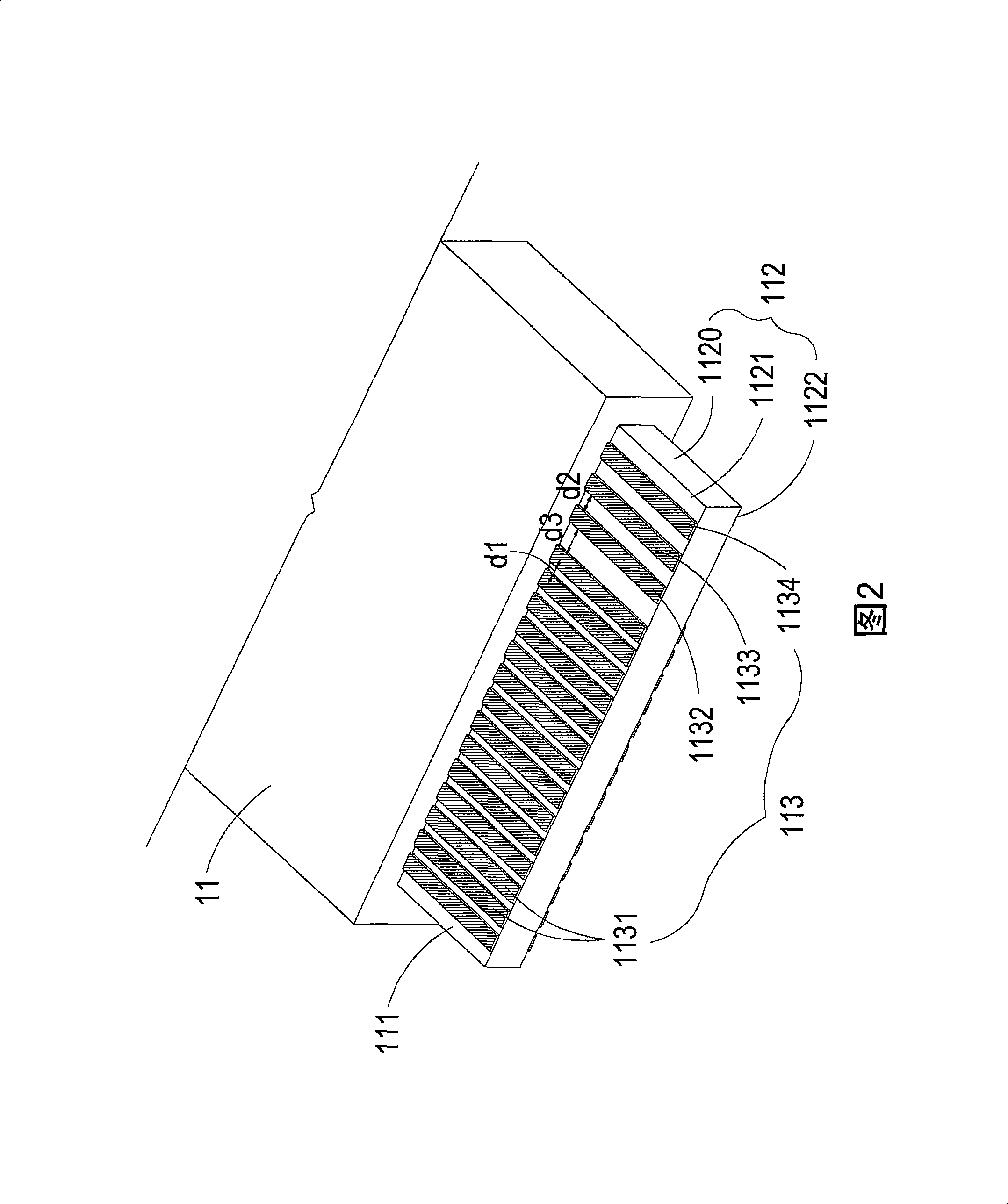
Since the second pin 1132 and the third pin 1133 for transmitting the AC power are formed on the same surface of the edge region 1120 of the circuit board 112 , the second pin 1132 and the third pin 1133 not only occupy the area of ​​the first surface 1121 Area area, and still need to reserve a considerable area for the second pin 1132 and the third pin 1133 to maintain a safe distance between the two pins, so, under the limited and fixed edge area width of the circuit board 112, make the second pin 1132 The total number of pins 1131 that can be set is relatively small, because the energy that can be transmitted by each first pin 1131 is fixed, so it indirectly affects the power transmission capacity of the power connection interface 111

Method used


Image

  • Electronic device with electric power connection interface
  • Electronic device with electric power connection interface
  • Electronic device with electric power connection interface

Examples


Embodiment Construction

[0048] Some typical embodiments embodying the features and advantages of the present invention will be described in detail in the following description. It should be understood that the present invention can have various changes in different ways, all of which do not depart from the scope of the present invention, and the description and drawings therein are essentially used as descriptions, rather than limiting the present invention. .

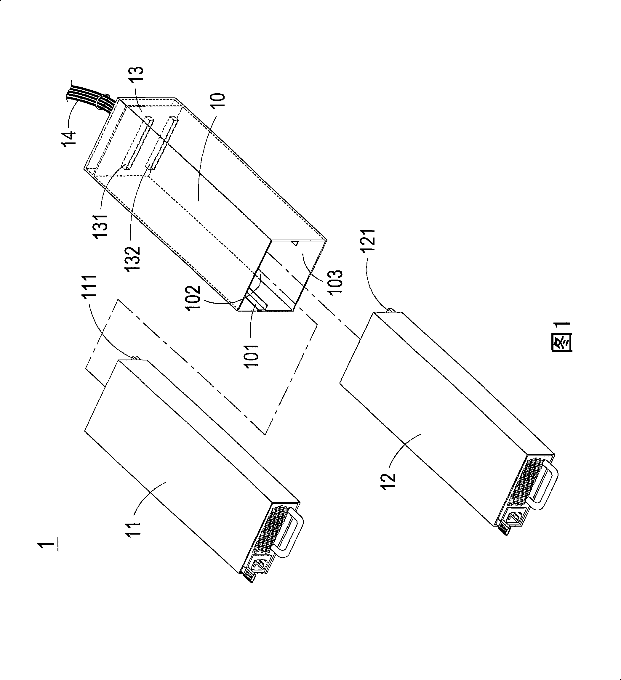
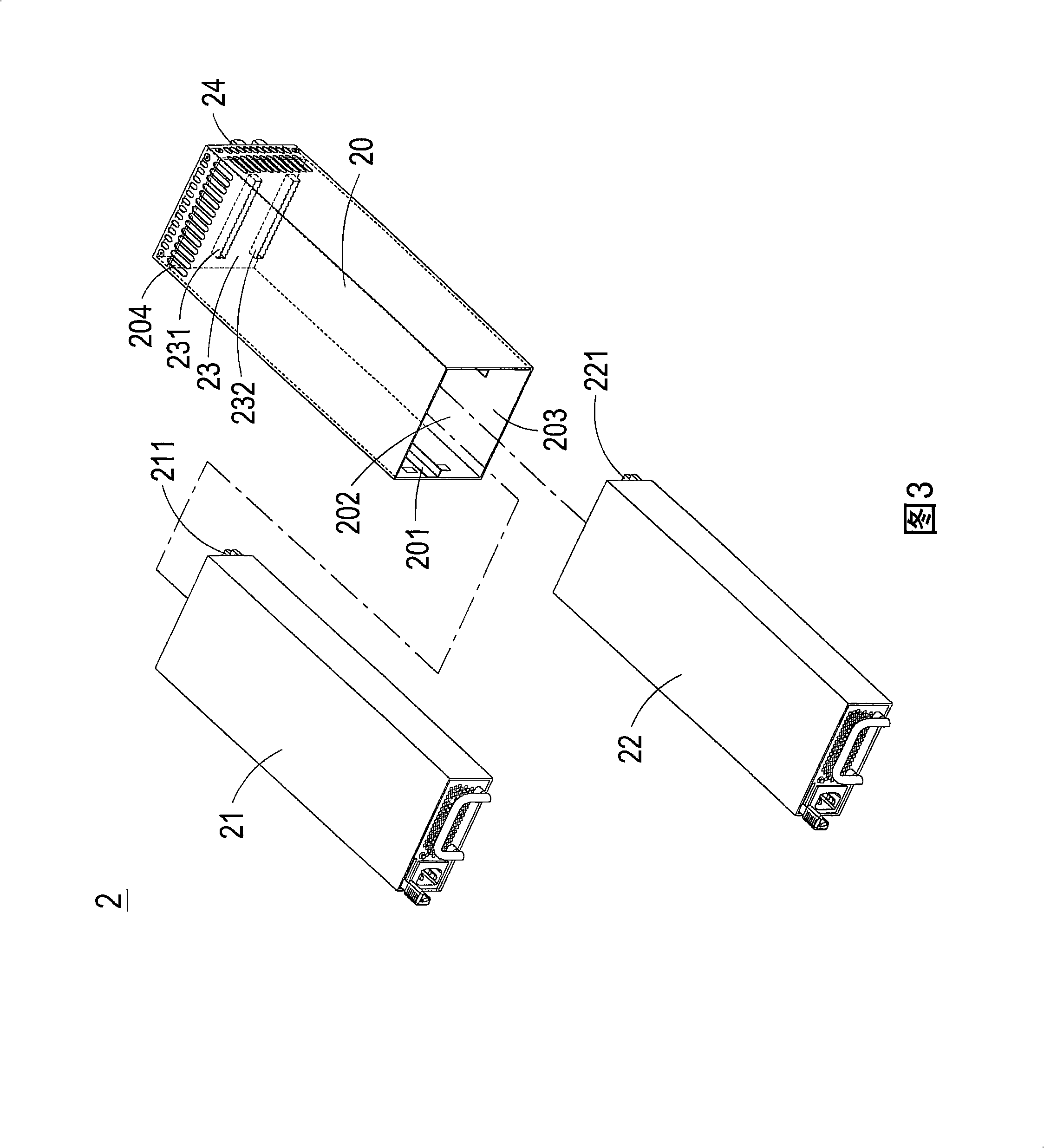
[0049] The present invention is an electronic device with a power connection interface, which is pluggably arranged in a body and connected with a corresponding slot in the body for transmitting power. The electronic device with a power connection interface of the present invention may be a pluggable power supply, for example, and is not limited thereto. In the following, a power supply with a power connection interface suitable for a redundant power supply system will be taken as an example to illustrate the technology of the present invention. ...


PUM


Abstract

The invention provides an electronic device with a power connecting interface, which at least comprises an electronic device. The power connecting interface is arranged on the electronic device and at least comprises a circuit board and a plurality of pins, wherein, the circuit board is provided with an edge area which comprises a first surface and a second surface; the pins at least comprise a plurality of first pins which transmit DC power and a second pin and a third pin which transmit AC power, wherein, the plurality of first pins are arranged on the first surface and the second surface, and the second pin and the third pin are positioned on different surfaces. The electronic device is arranged on different surfaces of the edge area of the circuit board by utilizing the live wire pin and the ground wire pin of the power connecting interface, thus causing the power connecting interface to have comparatively more areas for arranging the pin numbers for transmitting the DC power under the same width of the circuit board, enlarging the power of a power supply and improving the power density of the power supply.

Description

Technical field [0001] The invention relates to an electronic device with a power connection interface, in particular to a power supply with a power connection interface. Background technique [0002] The power supply system is an indispensable equipment for maintaining normal operation of various equipment, such as communication equipment, industrial computers, communication equipment or servers. In order to prevent the failure of the power supply system and the inability to continue power supply, which may even lead to the damage of the power-using equipment or the loss of data, a redundant power supply system (Redundant power supply system) was developed. The main principle of the redundant power supply system is to install two or more power supplies in parallel in a body. In normal operation mode, the power supply can share the energy provided to the load, but when one of the power supplies fails When power is not available, another power supply can continue to provide power....

Claims


Application Information

Patent Timeline
Patent Type & Authority Applications(China)
IPC IPC(8): H02M1/00H01R24/00H01R24/08H05K7/00H02J9/00H01R24/62
Inventor 皮尔圣塔那高尔·强伟特林振发李然
Owner DELTA ELECTRONICS (THAILAND) PUBLIC CO LTD
Learn More