Non-bearing switch reluctance motor complete-period electrification operating control method

A technology for switched reluctance motor and power generation operation, which is applied in the direction of controlling the shape/style/structure of generators and winding conductors through magnetic field changes, which can solve the problem of limiting the application range, weakening the application advantages of switched reluctance motors, and increasing permanent magnets, etc. question

Inactive Publication Date: 2008-11-05
NANJING UNIV OF AERONAUTICS & ASTRONAUTICS
View PDF0 Cites 15 Cited by
  • Summary
  • Abstract
  • Description
  • Claims
  • Application Information

AI Technical Summary

Problems solved by technology

However, none of them combine the improvement of power density with the high-speed adaptability of switched reluctance motors. The practice of adding permanent magnets even weakens the application advantages of switched reluctance motors in harsh operating environments, thus limiting its application range

Method used


Image

  • Non-bearing switch reluctance motor complete-period electrification operating control method
  • Non-bearing switch reluctance motor complete-period electrification operating control method
  • Non-bearing switch reluctance motor complete-period electrification operating control method

Examples


Embodiment Construction

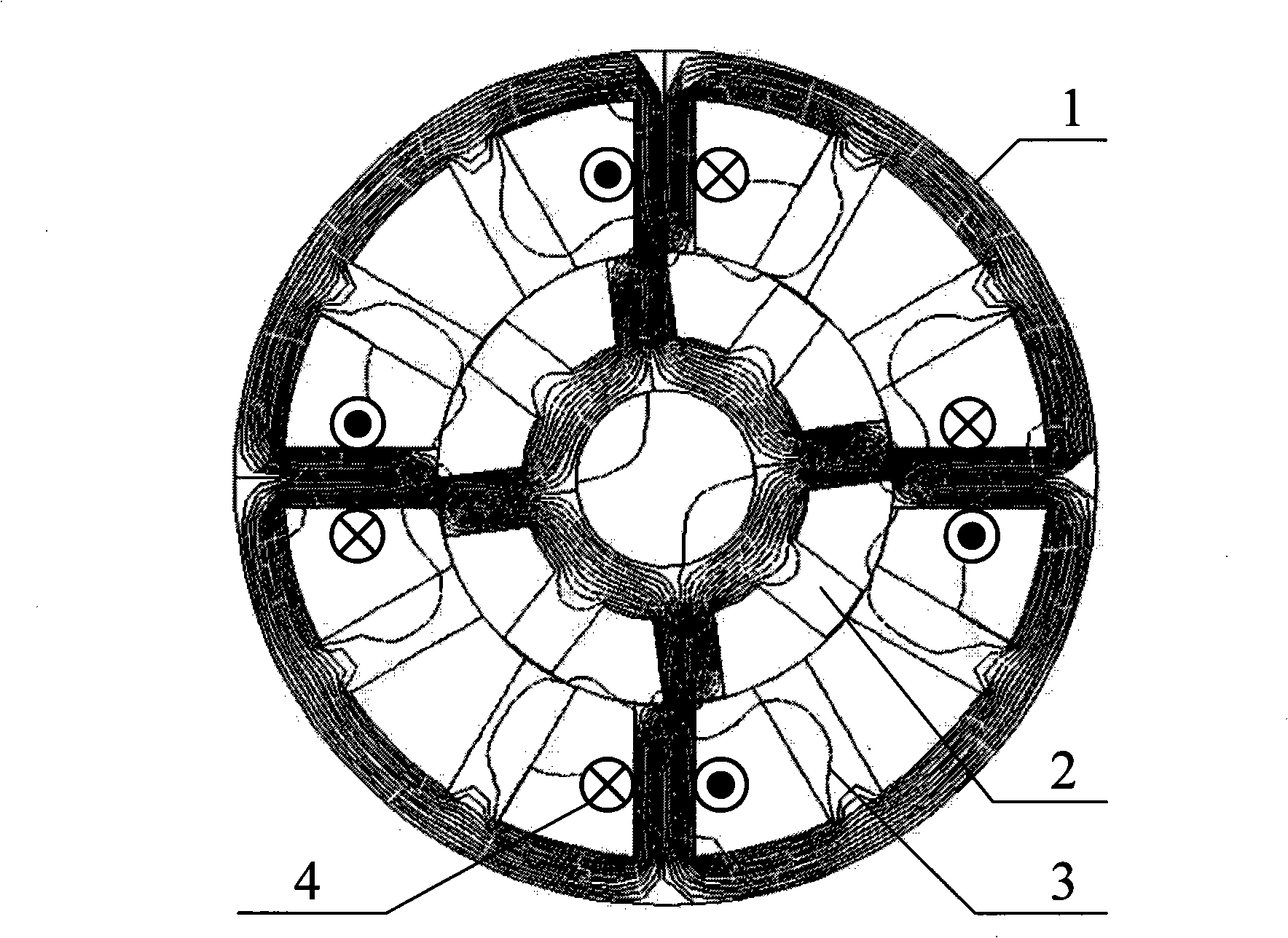
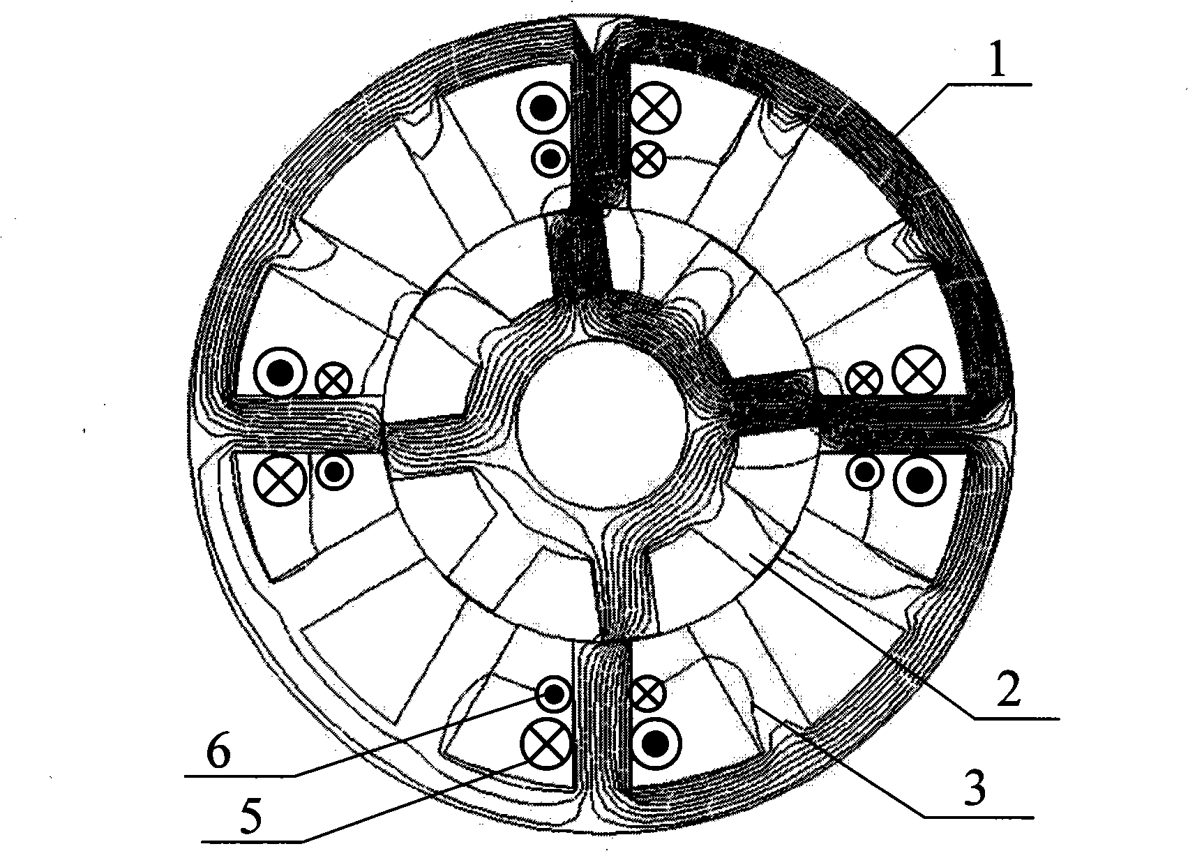
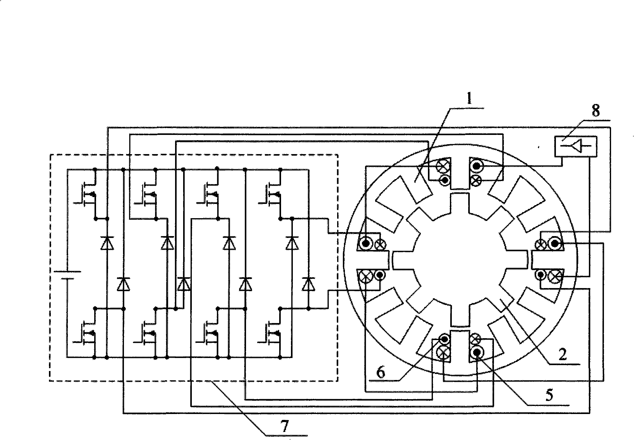
[0013] 1. Take the 12 / 8 bearingless switched reluctance generator as an example. Such as image 3 As shown, the suspension windings on each stator tooth are controlled independently, while the main windings on the four stator teeth of each phase are connected in series to form a full-cycle generator winding. The power converter of the suspension winding adopts an asymmetrical half-bridge power converter structure, and other types of power converters can also be used; the main winding is in a full-cycle power generation state, and the DC load can be powered by simply connecting the winding output terminal to the rectifier .

[0014] 2. If image 3 As shown, taking the two suspension windings in the horizontal direction as an example, the suspension winding on the right is fed with a larger current, and the suspension winding on the left is fed with a smaller current, resulting in the magnetic density of the right air gap being greater than that of the left air gap in the hori...


PUM


Abstract

The invention relates to a bear-free switch magnetic resistance motor complete period generating operation control method, belonging to the generation technology of the bear-free switch magnetic resistance motor. In the method, the suspension coil on each of the stator tooth pole is controlled independently, and the main coil connected in series on the stator tooth pole composes the complete period generation coil. Through controlling the different current of the opposite two suspension coils radially, the air gap field built by the two suspension coils is unbalanced, to generate the asymmetric radial magnetic pull. While the suspension coil current used as the generated exciting current provides the excitation energy to the main coil in the complete period, wherein the main coil outputs the electric energy to provide to the load after rectifying as the generating coil, which realizes the complete period generation of the bear-free switch magnetic resistance motor, effectively advances the availability of the suspension coil and the power density of the bear-free switch magnetic resistance motor, settles the basis for the application of the high speed generating field with high power density request.

Description

1. Technical field [0001] The invention relates to a method for controlling the power generation operation of a bearingless switched reluctance motor, which belongs to the power generation technology of a bearingless switched reluctance motor. 2. Background technology [0002] Switched reluctance motor (hereinafter referred to as SRM) has the characteristics of simple structure, convenient maintenance, low cost, high temperature resistance, high fault tolerance and inherent high-speed adaptability, and has important applications in aerospace, military, civil and other fields feature. Bearingless switched reluctance motor (hereinafter referred to as BSRM), which integrates the functions of magnetic bearing and motor, realizes the operation of magnetic levitation at the same time, because it does not need an independent radial magnetic bearing, the volume and weight are greatly reduced. The power density can be further increased. figure 1 , figure 2 They are the cross-sect...

Claims


Application Information

Patent Timeline
Patent Type & Authority Applications(China)
IPC IPC(8): H02K3/28H02P9/14
Inventor 曹鑫邓智泉王晓琳唐小洁杨钢
Owner NANJING UNIV OF AERONAUTICS & ASTRONAUTICS
Why Eureka
Try Eureka