
Real time monitoring system

A real-time monitoring and power supply technology, applied in general control systems, control/regulation systems, program control, etc., to solve problems such as inability to repair public facilities in time, heavy business burdens, and inability to improve the service quality of public institutions, reducing manpower The effect of resource consumption

Inactive Publication Date: 2008-11-19
BEYOND INNOVATION TECH
View PDF0 Cites 4 Cited by
  • Summary
  • Abstract
  • Description
  • Claims
  • Application Information

AI Technical Summary

Problems solved by technology

This approach not only consumes huge human resources, but also cannot repair existing public facilities in time
In contrast, the service quality of public institutions cannot be improved naturally, and their business burden is also becoming heavier day by day

Method used


Image

  • Real time monitoring system
  • Real time monitoring system
  • Real time monitoring system

Examples


Embodiment Construction

[0018] The main technical feature of the present invention is to use the combination of the signal generator and the public facilities, so that the management and control center monitoring the public facilities can obtain the usage status of the public facilities in real time, thereby reducing the consumption of human resources and achieving the effect of timely maintenance. The real-time monitoring system of the present invention will be illustrated below, but it is not intended to limit the present invention. Those skilled in the art can slightly modify the following embodiments according to the spirit of the present invention, but they still belong to the scope of the present invention.

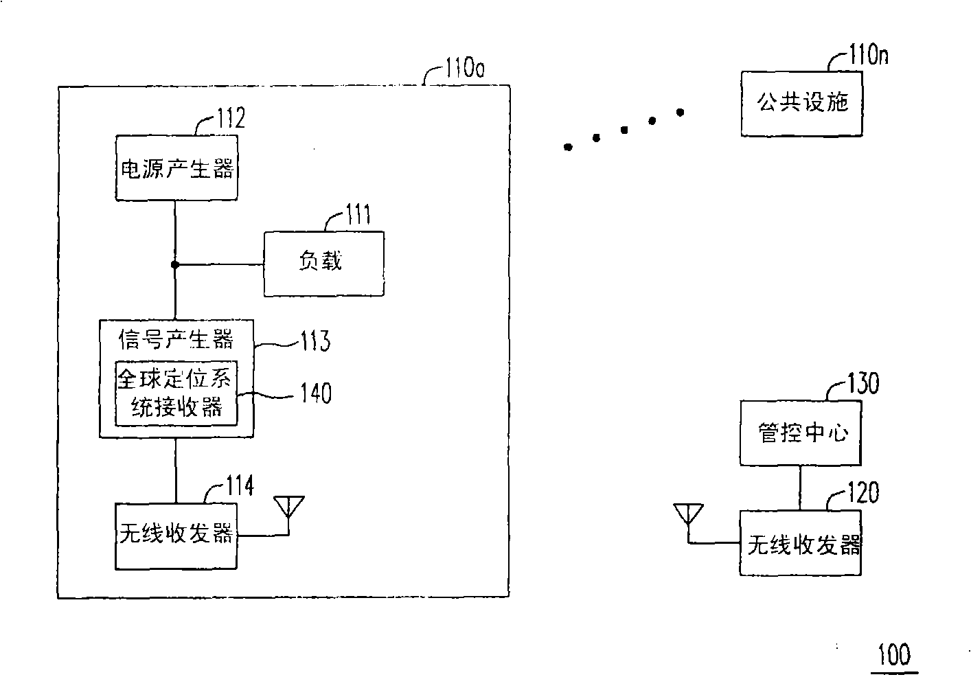
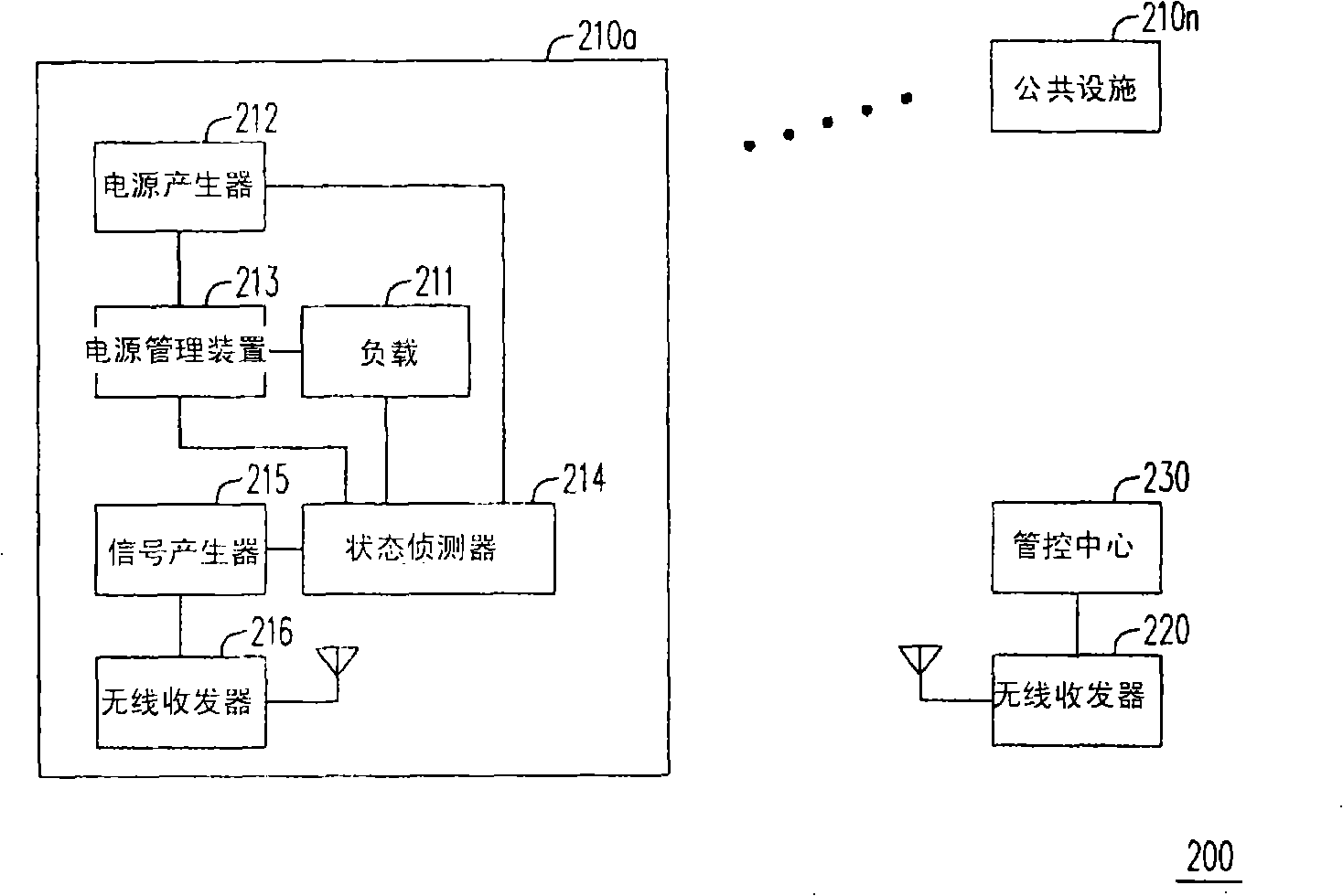
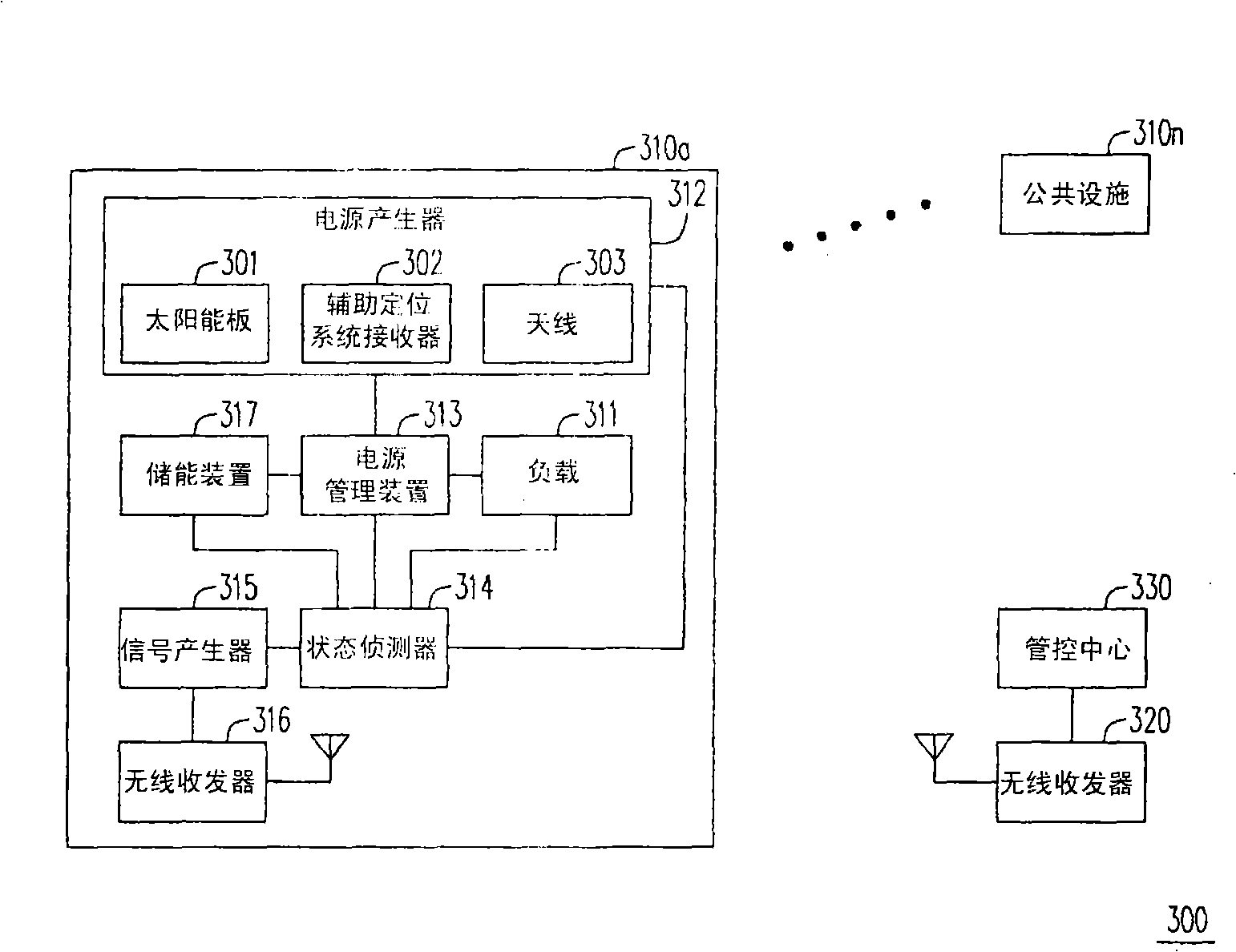
[0019] Please refer to figure 1 Shown is a real-time monitoring system according to an embodiment of the present invention. The real-time monitoring system 100 of this embodiment includes a plurality of public facilities 110 a - 110 n , a wireless transceiver 120 and a control center 130 ....


PUM


Abstract

A real-time monitoring system comprises at least a public facility, a second wireless transceiver and a control center; wherein, the public facility comprises a power generator, a load, a signal generator and a first wireless transceiver. The load is driven by the initial power supply provided by the power generator. The signal generator decides whether to output a status signal and a positioning signal or not based on the drive of the load. Later, the first wireless transceiver transmits the status signal and the positioning signal to the second wireless transceiver, so that the control center can judge the using status of the public facility based on whether the control center receives the status signal or all the information brought by the status signal, and can judge the location of the public facility according to the positioning signal.

Description

technical field [0001] The present invention relates to a real-time monitoring system, and in particular to a real-time monitoring system for managing and controlling public facilities. Background technique [0002] In order to improve the urban living and working environment, the government has managed various public facilities of public interest, such as traffic signs, street lights, telecommunication boxes, fire hydrants, etc. Here, the main purpose of public facilities is to enhance the convenience of public activities and ensure a good quality of life, so as to achieve direct, rapid and easy-to-feel substantiveness for the public. [0003] With the development of urbanization, the public facilities in the city are becoming more and more complicated, and the living environment is also full of various public facilities. Therefore, how to manage and maintain existing public facilities has become a topic that cannot be ignored in urban development. As far as the current m...

Claims


Application Information

Patent Timeline
IPC IPC(8): G05B19/048
Inventor 林久渊李扬汉叶汉国包又菘
Owner BEYOND INNOVATION TECH
Learn More