Teleconference device and sound emission/collection device

A sound collection and teleconferencing technology, applied in frequency/direction characteristic devices, sensor parts, sensors, etc., can solve problems such as large line resources

Active Publication Date: 2008-11-19
YAMAHA CORP
View PDF2 Cites 106 Cited by
  • Summary
  • Abstract
  • Description
  • Claims
  • Application Information

AI Technical Summary

Problems solved by technology

However, there is a problem that a large amount of wire resources must be used

Method used


Image

  • Teleconference device and sound emission/collection device
  • Teleconference device and sound emission/collection device
  • Teleconference device and sound emission/collection device

Examples


no. 1 example

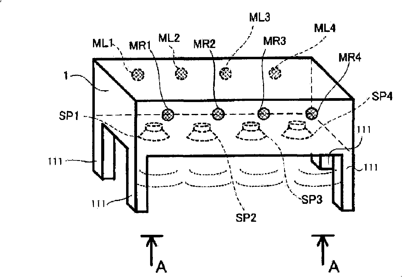
[0064] hereinafter will be referred to Figures 1A to 1C The structure and usage mode of the teleconferencing device as the first embodiment of the present invention will be described. The teleconferencing device of the first embodiment provides such a device: the speaker array is used to output the sound sent from the opposite device, thereby reproducing the speaker's position on the opposite device side, and the microphone array is used to pick up the speaker's voice, thereby Detect the position of the speaker, and then send the picked up sound and position information to the opposite device.

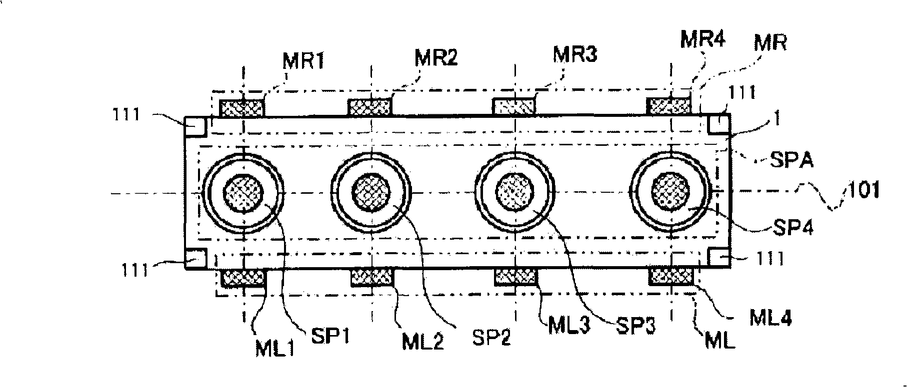
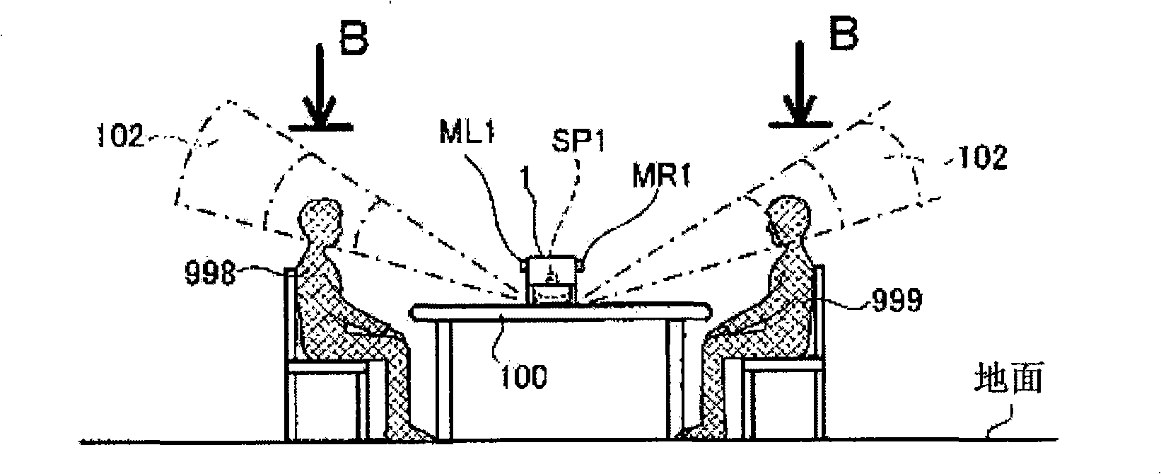
[0065] Figures 1A to 1C The external view and usage mode of the teleconferencing device are shown.Figure 1A is an external perspective view of the teleconferencing equipment, Figure 1B is the bottom view of the teleconferencing device along the arrow line A-A. and Figure 1C is a view of the usage pattern of the teleconferencing device.

[0066] Such as Figure 1A As shown, the...

no. 2 example

[0127] Next, a teleconferencing device according to a second embodiment will be described below with reference to FIG. 7 . This embodiment is an application of the first embodiment in FIG. 4, and the same reference numerals are assigned to the same parts in their description. Also, for the description of sound collection bundles, see Auxiliary image 3 .

[0128] In the first embodiment, the second estimating section 252 estimates on which side the real sound source exists on the assumption that the real sound source exists in one sound collection area of ​​the pair of sound collection areas where the difference signal is larger. In the second embodiment, the first beam generating section 231 and the second beam generating section 232 have detailed position search beam (narrow beam) generating functions 2313, 2323 for detailed analysis of the true beam estimated by the second estimating section 252, respectively. The sound collection area where the sound source is located is...

no. 3 example

[0137] Next, the sending part of the teleconferencing device according to the third embodiment of the present invention will be described below with reference to FIG. 8 . Fig. 8 is a block diagram of the transmission section. The difference of the transmission section 2 of the apparatus of this embodiment is that the outputs of the A / D converters 211, 212 are the inputs of the difference calculation circuit 22, and it is arranged to generate the first The third beam generating section 237 of the two collecting beams, the fourth beam generating section 238 and the fifth beam generating section 239 are provided, and the selectors 271, 272 are omitted. The same reference numerals are assigned to the same parts, and the above description applies to the remaining parts accordingly. Therefore, the differences and key points of the device of this embodiment will be described below.

[0138] As shown in FIG. 8 , the outputs of the A / D converters 211 , 212 are directly input to the d...


PUM


Abstract

A teleconference device includes a loudspeaker array and microphone arrays arranged at the both sides of the loudspeaker array. A plurality of focal points are set in front of the respective microphone arrays and symmetrically with respect to the center line of the loudspeaker array. A flux of sound collection beams toward the focal points is outputted. By calculating a difference between the sound collection beams toward the focal points symmetric with respect to the center line, a sound component coming into the microphone from the loudspeaker array SPA is cancelled. Furthermore, a total of squares of wave height value of the difference value for a particular time is used to estimate which of the set focal points is the nearest. Furthermore, by comparing the totals of squares of the wave height values of the sound collection beams toward the focal points symmetric to each other, it is possible to judge the position of the speaker.

Description

technical field [0001] The present invention relates to devices having a microphone array and a loudspeaker array for reproducing received sound and sound fields, and more particularly to techniques for specifying the position of a speaker or sound source relative to the microphone array. Background technique [0002] In the prior art, devices for receiving sound on the transmitter side and reproducing the sound field of the sound on the transmitter side have been proposed (see Patent Documents 1 to 3). In such an apparatus, sound signals and the like picked up by a plurality of microphones are transmitted, and a sound field on the transmitter side is reproduced by a plurality of speakers on the receiver side. This device has the advantage that the position of the speaker can be specified by sound. [0003] In Patent Document 1, there is disclosed a creation method of stereo information, etc., by transmitting sound information received by a plurality of microphone arrays, a...

Claims


Application Information

Patent Timeline
Patent Type & Authority Applications(China)
IPC IPC(8): H04R3/00H04R1/40
Inventor 石桥利晃铃木智田中良鹈饲训史
Owner YAMAHA CORP
Why Eureka
Try Eureka