No-key vehicle tap lock

A faucet lock and key-free technology, which is applied to bicycle accessories, devices to prevent bicycle theft, transportation and packaging, etc., can solve the problem of motorcycle theft

Inactive Publication Date: 2008-11-26
FORMOSA SEIKO ELECTRONICS +1
View PDF0 Cites 13 Cited by
  • Summary
  • Abstract
  • Description
  • Claims
  • Application Information

AI Technical Summary

Problems solved by technology

[0004] After the power supply lock of the existing locomotive is t...

Method used


Image

  • No-key vehicle tap lock
  • No-key vehicle tap lock
  • No-key vehicle tap lock

Examples


Embodiment Construction

[0044] The structural design of the present invention will be further described with reference to the accompanying drawings by way of examples but not limiting embodiments:

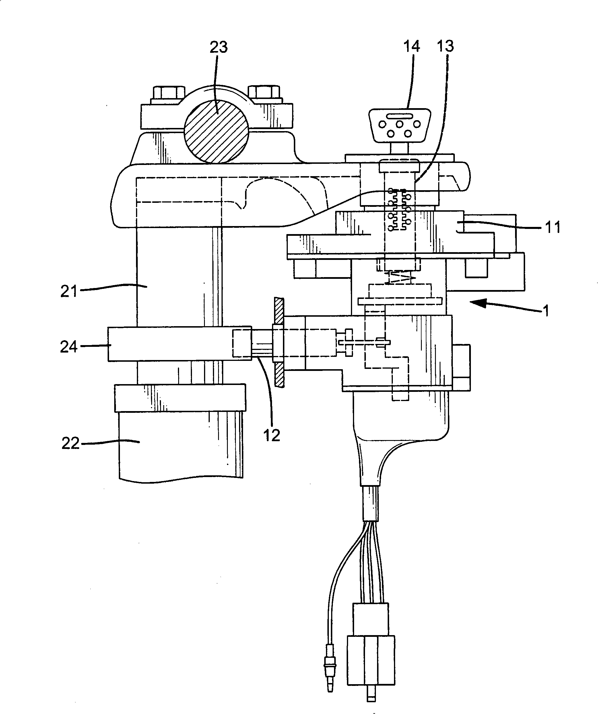
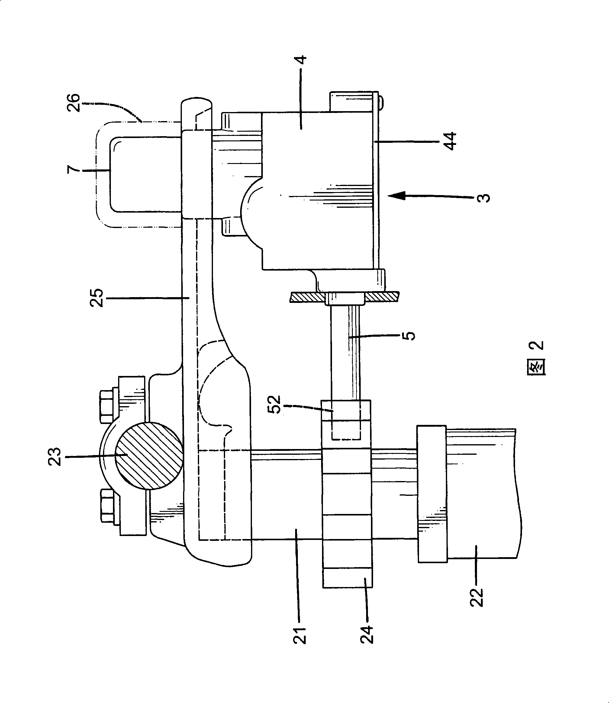
[0045] Please refer to FIG. 2 , which shows a schematic view showing that the motorcycle faucet lock 3 formed according to an embodiment of the present invention is installed near the steering shaft 21 of the handlebar of the motorcycle. The handle 23 of the locomotive is installed on the top of the steering shaft 21 to control the steering of the locomotive.

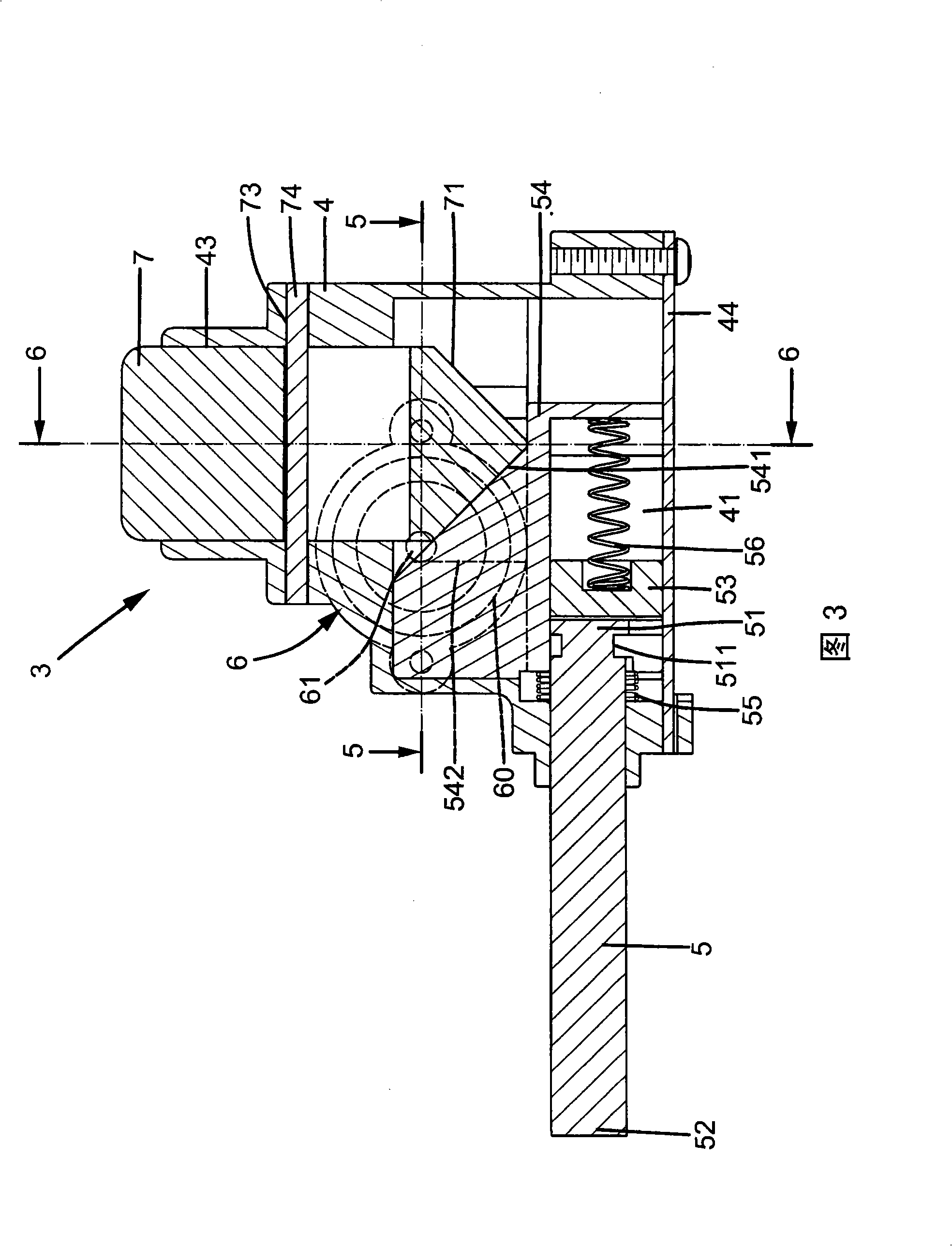
[0046] Cooperate with Figure 3 and Figure 4 , showing the specific structure of the motorcycle faucet lock 3 of the present invention, which includes a body 4, a locking pin 5 located in the body 4, an unlocking device 6 and a locking operating member 7; in this embodiment, as shown in Figure 2 Shown, the body 4 is installed on the supporting plate 25 disposed on the upper end of the steering shaft 21 of the motorcycle handle, and the locking pin...


PUM


Abstract

The invention discloses a keyless locomotive handle lock, which comprises a body, a locking pin arranged in the body, an unlocking device and a locking operation component; the locking pin can move between a stretching position to lock a locomotive handle (handle) and a retracting position to release the locomotive handle; the unlocking device comprises an electromagnetic switch which can be controlled by a signal receiver and a movable locking rod which can be controlled by the electromagnetic switch; the locking operation component is a manual button; when operating the button, the locking pin moves to the stretching position to lock the locomotive handle; by operating a corresponding remote control, the electromagnetic switch is driven to abstract the locking rod to move back to the retracting position so as to release the locomotive handle, thereby achieving the control of the locking and unlocking of the locomotive handle without using a key.

Description

technical field [0001] The invention relates to a keyless locomotive faucet lock, in particular to an anti-theft device capable of preventing the handle of the locomotive from turning. Background technique [0002] In order to prevent locomotives from being stolen, almost all locomotives are equipped with spigot locks to prevent the locomotive handle from turning, thereby making the locomotive unable to move. [0003] Existing locomotive faucet lock is usually set together with locomotive power supply lock, as figure 1 As shown, an existing locomotive power supply lock 1 is installed near the steering shaft 21 of the locomotive. To control the steering of the locomotive, the inside of the lock body 11 of the power lock 1 is provided with a locking pin 12 that can prevent the handle 23 from rotating; After 14 rotates to locked position, this locking pin 12 will be driven to stretch out and embed the locking plate indicated by label 24 and lock, and when this locking pin 12 ...

Claims


Application Information

Patent Timeline
IPC IPC(8): B62H5/02
Inventor 林瑞昌许芳毓
Owner FORMOSA SEIKO ELECTRONICS
Why Eureka
Try Eureka