Full-view cooperative video monitoring apparatus and full-view image splicing method

A technology of video surveillance and monitoring device, which is applied in the field of panoramic linkage video surveillance device, can solve the problems such as partial enlargement of suspicious areas or key areas, small angle of monitoring field of view, poor quality of recorded images, etc., and achieves a high level of technological innovation, The monitoring field of view has a wide range of angles and the effect of avoiding monitoring dead ends.

Inactive Publication Date: 2008-11-26
TIANJIN YAAN TECH CO LTD
View PDF1 Cites 52 Cited by
  • Summary
  • Abstract
  • Description
  • Claims
  • Application Information

AI Technical Summary

Problems solved by technology

Existing video surveillance devices generally have problems such as small monitoring field of view angle, poor video quality, inability to partially zoom in on suspicious areas or key areas, and inability to implement target detection, behavior recognition, and automatic alarms based on object behavior characteristics.
In order to overcome the above problems, the patent application "An electronic navigation positioning camera monitoring system" (application number: 200610015336.0) introduces an electronic navigation monitoring device that combines a panoramic static camera and a moving camera. Surveillance of panoramic video, but the still camera used is a wide-angle camera, and its panoramic image is obtained by using the optical characteristics of a fisheye lens, and the collected image will be deformed to a certain extent, thus reducing the quality of the recorded image; in addition, Multiple wide-angle cameras cannot transmit their respective images to the background monitoring equipment at the same time, and must be controlled by an electronic switch to transmit the image of each wide-angle camera to the back-end monitoring equipment, so it is still not possible to completely solve the problem of monitoring without dead ends

Method used


Image

  • Full-view cooperative video monitoring apparatus and full-view image splicing method
  • Full-view cooperative video monitoring apparatus and full-view image splicing method
  • Full-view cooperative video monitoring apparatus and full-view image splicing method

Examples


Embodiment Construction

[0026] The embodiments of the present invention are described in further detail below in conjunction with the accompanying drawings. The following embodiments are only descriptive, not restrictive, and cannot limit the protection scope of the present invention. Those skilled in the art can draw according to the technical solutions of the present invention. Other implementation modes also belong to the protection scope of the present invention.

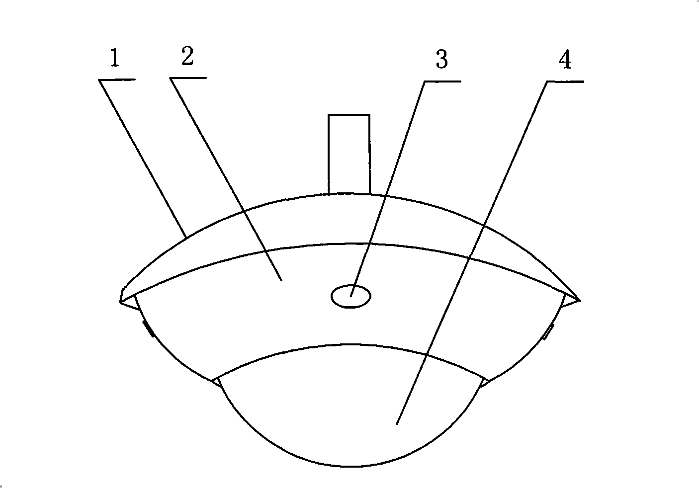
[0027] This panoramic linkage video monitoring device is composed of a monitoring device 1, a moving camera 2 and a still camera 3. The moving camera can perform horizontal rotation, pitching, and zooming actions, and a high-zoom camera is used to track and zoom in on partial images; N sets of still cameras Evenly installed on the outer cover of the monitoring device 1, the 360-degree panorama can be monitored in real time. The number N of still cameras is 2 to 9, and its number N=360°. The field of view of the still cameras is wide, th...


PUM


Abstract

The invention relates to a panoramic linkage video monitoring device and a splicing method of panoramic images, belonging to the video monitoring technical field, wherein the panoramic linkage video monitoring device is composed of a monitoring device and a motion camera, and the motion camera is provided in the monitoring device. The invention is characterized in that the cover of the monitoring device is uniformly provided with N stable cameras, and the pictures of the N stable cameras are spliced into a panoramic image, the monitoring device is provided with a control circuit for controlling the linkage between the video images of the stable cameras and the motion camera. The invention adopts the linkage between the motion camera and the stable cameras, having high image quality, large monitoring angle range and the ability for tracking and amplifying the picture of any area in the view angle range. The invention combines panoramic image and local amplified image to improve the security level of the monitoring device, which has high technical level and wide application.

Description

technical field [0001] The invention belongs to the field of video monitoring, in particular to a panoramic linkage video monitoring device and a method for splicing panoramic images thereof. Background technique [0002] At present, places such as banks, stock exchanges, shopping malls, and high-end office buildings have installed video surveillance devices, effectively improving the security capabilities of these places. Existing video surveillance devices generally have problems such as small monitoring field of view, poor video quality, inability to partially zoom in on suspicious areas or key areas, and inability to implement target detection, behavior recognition, and automatic alarms based on object behavior characteristics. In order to overcome the above problems, the patent application "An electronic navigation positioning camera monitoring system" (application number: 200610015336.0) introduces an electronic navigation monitoring device that combines a panoramic st...

Claims


Application Information

Patent Timeline
Patent Type & Authority Applications(China)
IPC IPC(8): H04N7/18G06T5/00
Inventor 邓兴波
Owner TIANJIN YAAN TECH CO LTD
Why Eureka
Try Eureka