Electronic apparatus installation structure and pneumatic tire

An electronic device and pneumatic tire technology, applied in the direction of tire measurement, measuring devices, tire parts, etc., can solve complex problems such as repair and replacement

Active Publication Date: 2008-12-17
BRIDGESTONE CORP
View PDF1 Cites 17 Cited by
  • Summary
  • Abstract
  • Description
  • Claims
  • Application Information

AI Technical Summary

Problems solved by technology

However, in this way, it is difficult to detach the above-mentioned electronic device from the above-mentioned airtight layer, and the operations such as repairing and replacing the above-mentioned electronic device become complicated.

Method used


Image

  • Electronic apparatus installation structure and pneumatic tire
  • Electronic apparatus installation structure and pneumatic tire
  • Electronic apparatus installation structure and pneumatic tire

Examples


no. 1 Embodiment approach

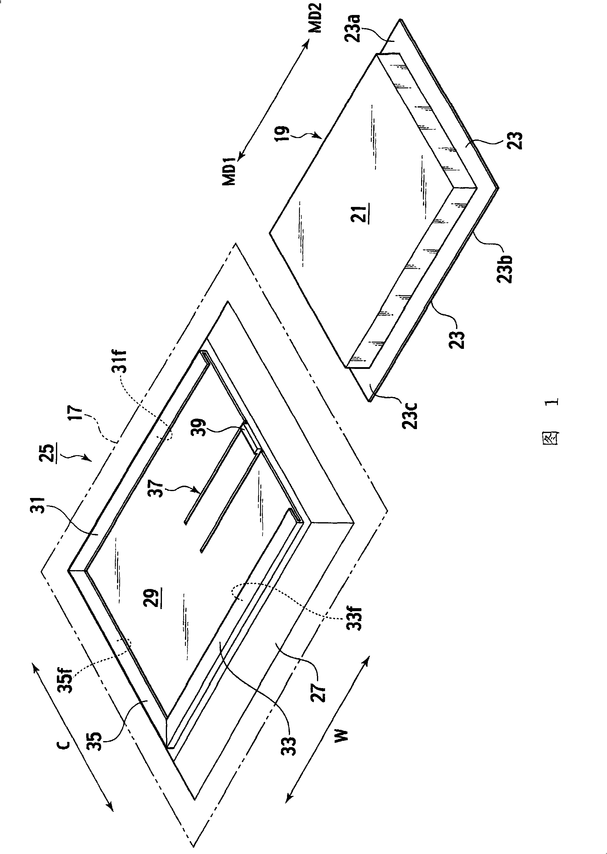
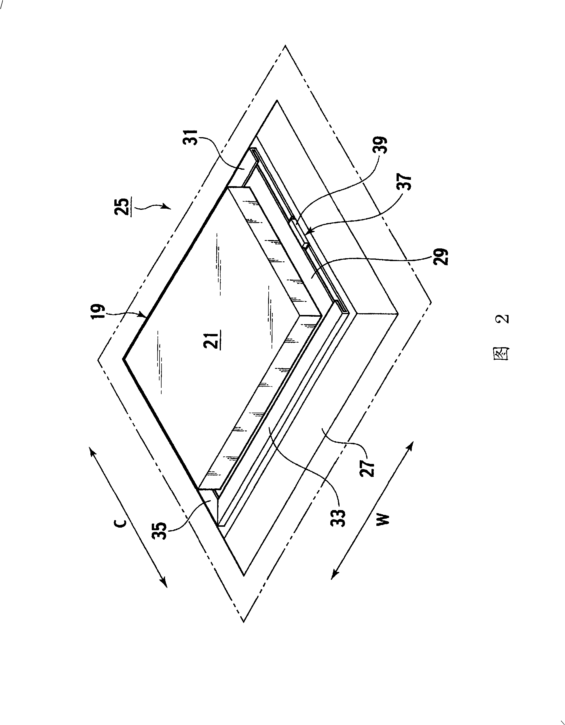
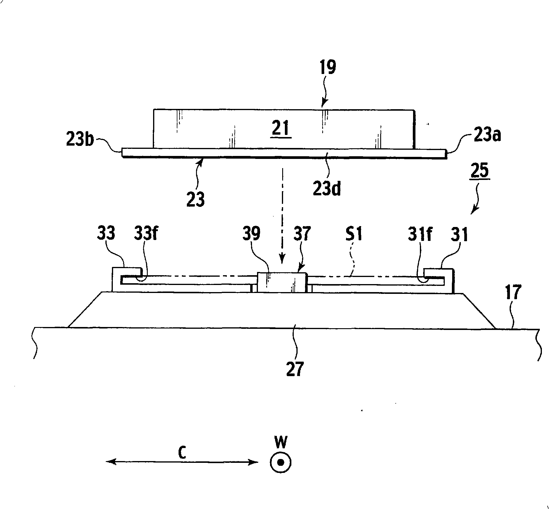
[0043] Refer to Figure 1~ Figure 5 A first embodiment of the present invention will be described.

[0044] Such as Figure 5 As shown, the pneumatic tire 1 according to the first embodiment can be filled with air as working gas, and includes a pair of annular filler strips 5 which can be fitted to the rim 3 . A bead core 7 is built into each bead filler 5 . In addition, a ply 9 as a skeleton member is integrally provided between the pair of filler beads 5 . The carcass layer 9 has a circular cross-sectional shape. A multilayer belt layer 11 is also provided on the outer peripheral surface of the carcass layer 9 .

[0045] A tread 13 capable of contacting the ground is integrally provided on the outer peripheral surface of the carcass layer 9 , and the tread 13 covers the belt layer 11 . Sidewalls 15 for protecting the carcass 9 are integrally provided on the outer surfaces of the carcass 9 . In addition, the inner surface (including the inner peripheral surface) of the ...

no. 2 Embodiment approach

[0061] refer to Figure 6 ~ Figure 11 A second embodiment of the present invention will be described.

[0062] Such as Figure 11 As shown, the pneumatic tire 41 of the second embodiment includes a pair of bead fillers 5, a bead core 7, a carcass 9, a multilayer belt 11, a tread 13, sidewall 15 and inner liner 17 . In the figure, among the plurality of constituent elements of the pneumatic tire 41 of the second embodiment, members corresponding to the constituent elements of the pneumatic tire 1 of the first embodiment are given the same reference numerals, and description thereof will be omitted.

[0063] Such as Image 6 As shown, a wireless transponder 43 is installed on the peripheral surface of the airtight layer 17 . The wireless repeater 43 includes a box-shaped electronic device main body 45 in which various electronic components (not shown) are built. In addition, a circular device plate 47 made of a light alloy such as aluminum is provided on the bottom of the e...


PUM


Abstract

An electronic apparatus is installed on a peripheral surface of an inner liner with a first edge, a second edge, and a third edge of a device plate held between a first support surface of a first guide tab and the surface of a support plate, between a second support surface of a second guide tab and the surface of the support plate, and between a third support surface of a third guide tab and the surface of the support plate. The electronic apparatus is easily held installed in a stable manner for a long period and the apparatus can be easily removed from the peripheral surface of the inner liner.

Description

technical field [0001] The present invention relates to an electronic device mounting structure for mounting an electronic device (electronic device) such as a wireless repeater, a tire internal pressure monitoring device, etc., on an inner liner of a pneumatic tire, and the electronic device mounted by the above electronic device mounting structure pneumatic tires. Background technique [0002] As a prior art of an electronic device mounting structure for mounting an electronic device such as a wireless repeater on an inner liner of a pneumatic tire, there is one disclosed in Patent Document 1. The specific configuration of this prior art electronic device mounting structure is as follows. [0003] That is, a rubber seat (a rubber carcass (130) in Patent Document 1) is attached to the inner liner. An attachment shaft (shaft (152) in Patent Document 1) is integrally provided at the center of this rubber base. A mounting head (in Patent Document 1, the head of the shaft ( ...

Claims


Application Information

Patent Timeline
Patent Type & Authority Applications(China)
IPC IPC(8): B60C23/04B60C19/00G01L17/00
CPCB60C23/0493
Inventor 内海敦郎渡边洋一古川真市川良彦
Owner BRIDGESTONE CORP
Why Eureka
Try Eureka