Color-band guide parts and printing device

A technology for guiding components and printing devices, applied in the direction of inking devices, printing, etc., which can solve problems such as ink smearing

Active Publication Date: 2008-12-31
OKI ELECTRIC IND CO LTD
View PDF1 Cites 0 Cited by
  • Summary
  • Abstract
  • Description
  • Claims
  • Application Information

AI Technical Summary

Problems solved by technology

[0006] However, in the structure of the conventional ribbon protection bracket, when the ribbon cassette is set on the printing device, as shown in FIG. The ink ribbon 15 must be picked up by hand to set it in the state shown in FIG.

Method used


Image

  • Color-band guide parts and printing device
  • Color-band guide parts and printing device
  • Color-band guide parts and printing device

Examples


Embodiment approach 1

[0032] (structure)

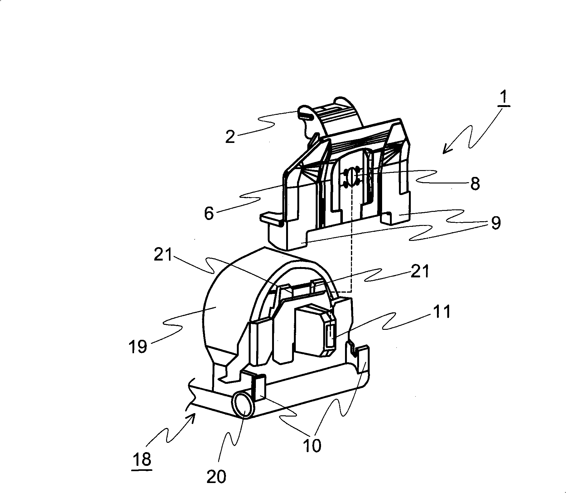
[0033] Figure 4 What is shown is the structure of the ribbon guide part and the printing device. 14 is an ink ribbon cassette, which has an ink ribbon 15 for printing on a printing medium not shown in the figure. The knob 16 is used to wind up the slack ribbon 15 by rotating the knob 16 when the ribbon 15 is slack.

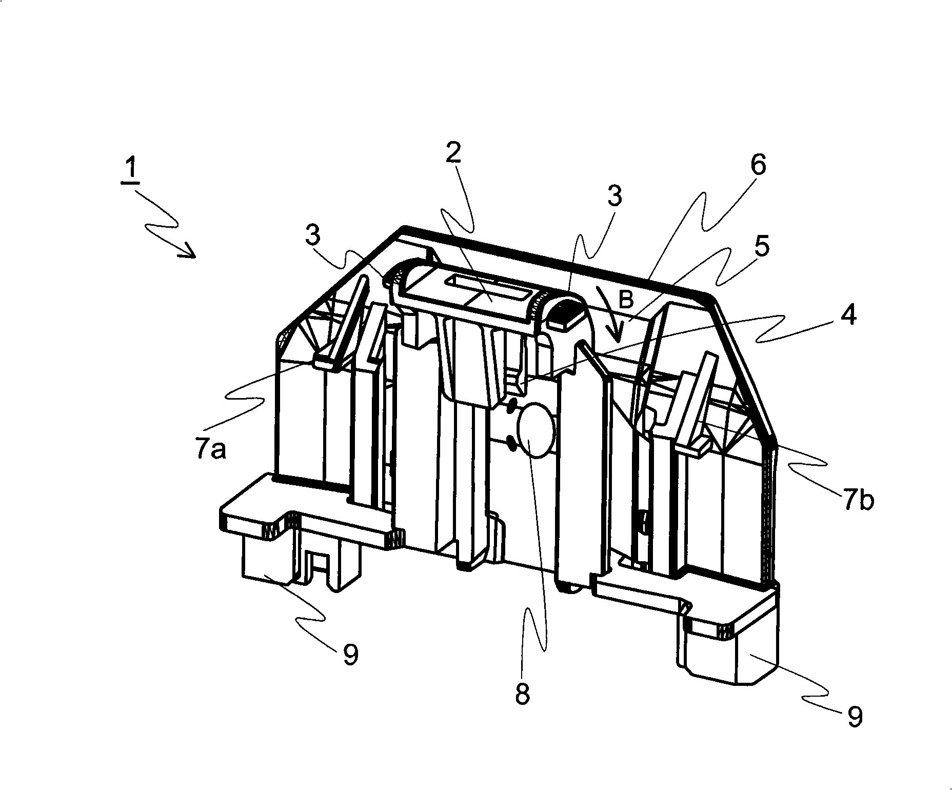
[0034] 1 is a ribbon guide member, which is composed of a guide part 2 and a ribbon protection bracket 6, and is a supporting part that supports the ribbon 15 to move freely. In addition, the ribbon guide member 1 can be detached from the ribbon cassette 14 and the printing device 13 .

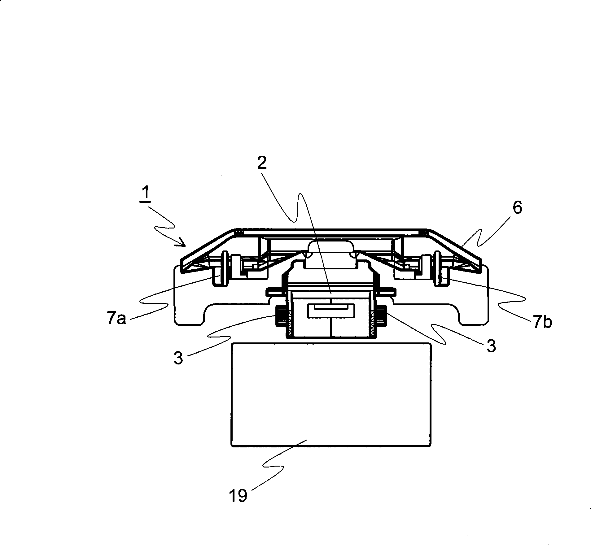
[0035] 13 is a printing device, and the printing head 19 writes printing information on the printing medium through the ribbon 15 supported by the ribbon guide member 1 .

[0036] The print head carriage 18 is loaded with the print head 19 and the ribbon protection bracket 6, along the carriage shaft 17 parallel to the platen 12, the spacing is adjusted i...

Embodiment approach 2

[0058] (structure)

[0059] Such as Figure 9 and Figure 10 As shown, in order to minimize the obstruction when the ribbon 15 is installed on the ribbon guide member, the ribbon guide member and the printing device of the second embodiment exclude the ribbon of the ribbon protection bracket 6 in the first embodiment. Guide part 7b. The other configurations are the same as those of the ribbon guide member and the printing device in Embodiment 1, and therefore detailed description thereof will be omitted.

[0060] in addition, Figure 9 and Figure 10 In order to more clearly show the ribbon guide part 7a, the guide part 2 already described in the first embodiment is omitted.

[0061] (action)

[0062] With the above structure, the ribbon guide member and the printing device according to Embodiment 2 can perform the following operations. Use the following Figure 11 The action description diagram in the figure explains this action in detail.

[0063] Figure 11 And in...


PUM


Abstract

The invention provides a printing apparatus for installing ribbon with dirtying hands and printing with ribbon. In the printing apparatus, a support section for supporting free movement of the ribbon 15 in a ribbon case, a guiding section 2 with slant on upper part, a ribbon protector 5 with upper part bending to a press paper reel side, and a meshing slice 4 for meshing the guiding section 2 and the a meshing section 21 on head of a printing head 19 are arranged on a ribbon guiding unit 1, and a, and an inosculating slice 9 inosculated with an inosculating section 10 of the printing apparatus head slide frame 18 is arranged.

Description

technical field [0001] The invention relates to a ribbon guide unit and a printing device. Background technique [0002] Generally, in an impact printer (impact printer) or the like (hereinafter referred to as "printing device") that prints on a medium such as printing paper through the impact of a print head on an ink ribbon, when installing the printing device and When the ribbon needs to be replaced due to its life, a ribbon cartridge must be mounted on the printing device. [0003] When the ink ribbon cassette is installed, the drive shaft protruding from the print head carriage of the printing device and the feed roller (feed roller) engage with each other, and the feed roller rotates due to the rotation of the drive shaft. The tape is fed and wound up simultaneously with printing or the like. [0004] In the past, when the ink ribbon cassette was set on the printing device, as shown in Figure 13, an unmarked ink ribbon cassette was set in the print head slide frame 1...

Claims


Application Information

Patent Timeline
IPC IPC(8): B41J33/02B41J35/04
Inventor 桥本宏基
Owner OKI ELECTRIC IND CO LTD
Why Eureka
Try Eureka