Mounting duct for sodium-cooled fast reactor inner sodium liquid level meter

A technology for installing channels and sodium-cooled fast reactors, which is applied in fast fission reactors, reactors, nuclear reactors, etc. good protective effect

Active Publication Date: 2008-12-31
CHINA INSTITUTE OF ATOMIC ENERGY
View PDF0 Cites 4 Cited by
  • Summary
  • Abstract
  • Description
  • Claims
  • Application Information

AI Technical Summary

Problems solved by technology

The liquid metal sodium in the sodium-cooled fast reactor is in a flowing state, and the flowing liquid sodium is easy to impact the liquid level gauge, and the sodium liquid l...

Method used


Image

  • Mounting duct for sodium-cooled fast reactor inner sodium liquid level meter
  • Mounting duct for sodium-cooled fast reactor inner sodium liquid level meter

Examples


Embodiment Construction

[0010] Below in conjunction with accompanying drawing and specific embodiment the present invention is described in further detail:

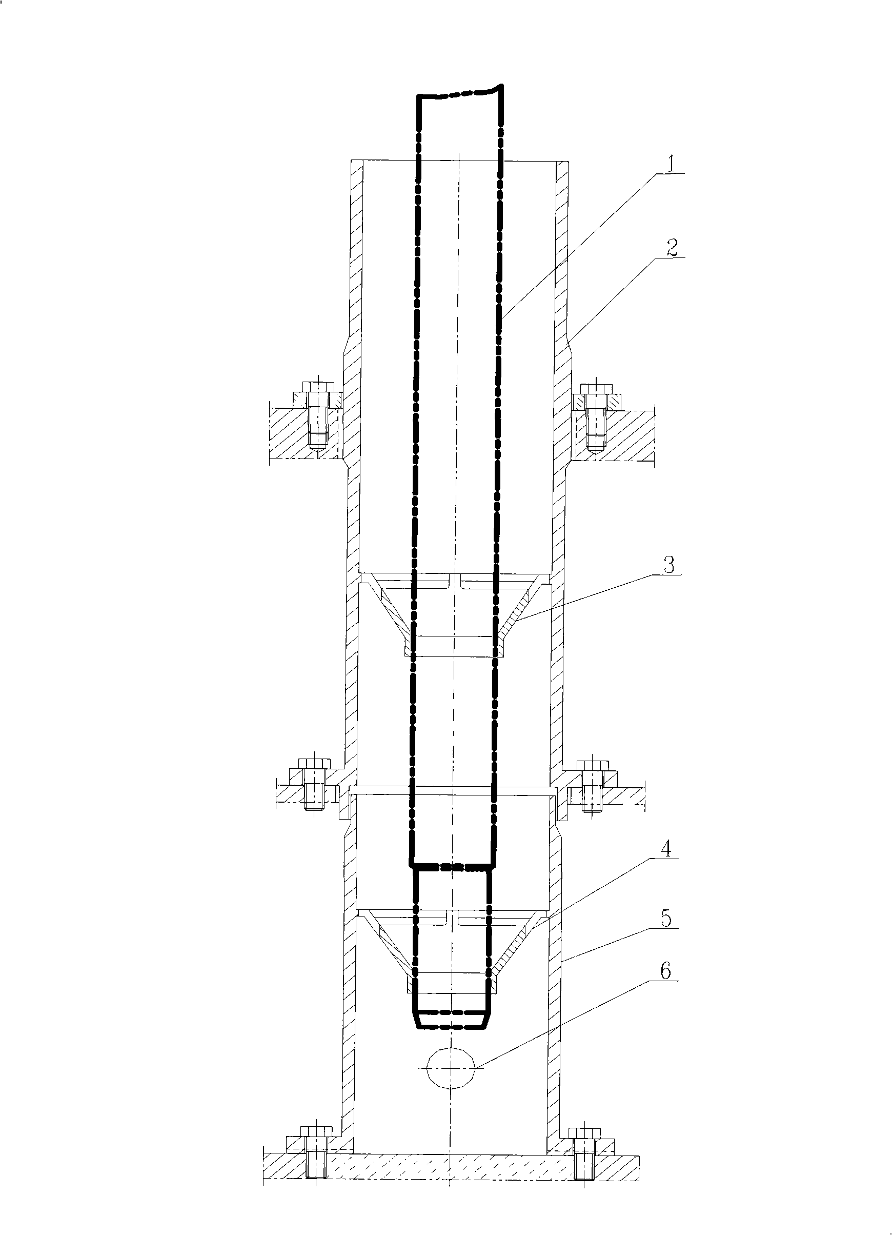
[0011] The installation channel of the sodium level gauge in the sodium-cooled fast reactor can be composed of one or more pipes of different lengths welded together, and the limiting parts inside the pipe can also use one or more to adjust the sodium level gauge 1 as required. position. In order to make pipeline processing and installation more convenient, such as figure 1 The present embodiment shown is composed of a circular upper pipe 2 and a lower pipe 5, wherein the upper pipe 2 and the lower pipe 5 are respectively connected with a conical piece 3, 4 as a limiting part of the sodium level gauge 1, and the upper The lower end and upper part of the pipeline 2, and the lower end of the lower pipeline 5 respectively use flanges to securely install the whole pipeline on the inner support and the inner shield of the pile. Have 2 holes 6 on th...


PUM


Abstract

The invention discloses an installation channel used for a sodium fluid level gauge in a sodium-cooled fast reactor. The channel of the invention comprises a pipeline with holes and a stop component is connected in the pipeline. In addition, the invention also provides an installation channel device which can carry out the locating and protection to the sodium fluid level gauge.

Description

technical field [0001] The invention relates to a positioning and protection device for a sodium liquid level gauge in a sodium-cooled fast reactor, in particular to an installation channel device for a sodium liquid level gauge in a sodium-cooled fast reactor. Background technique [0002] In the sodium-cooled fast reactor, the sodium level gauge is a slender device used to measure the height of the sodium level, and it is a safety monitoring device for the sodium level in the reactor. The liquid metal sodium in the sodium-cooled fast reactor is in a flowing state, and the flowing liquid sodium is easy to impact the liquid level gauge, while the sodium level gauge is slender and fragile, and the flowing liquid sodium can easily lead to inaccurate measurement of the sodium level gauge , and even cause damage to the liquid level gauge. Contents of the invention [0003] The invention overcomes the shortcomings of the prior art and provides an installation channel device fo...

Claims


Application Information

Patent Timeline
IPC IPC(8): G21C1/03G21C17/025
CPCY02E30/30
Inventor 孙刚尤吉堃鲍扬民金跃庆萧勋泽田传久
Owner CHINA INSTITUTE OF ATOMIC ENERGY
Why Eureka
Try Eureka