Teeth appliance

A dental appliance and tooth surface technology, applied in the field of orthodontic devices, can solve the problems of reducing the degree of freedom of the dental arch wire, unfavorable movement of the dental arch wire, troubles, etc.

Inactive Publication Date: 2009-01-14
宋芝春
View PDF0 Cites 12 Cited by
  • Summary
  • Abstract
  • Description
  • Claims
  • Application Information

AI Technical Summary

Problems solved by technology

[0002] The United States published the patent No. 4877398 on October 31, 1989, which discloses a dental appliance that can use light force to make the teeth move mesially and distally, without the need for external force anchorage and implant anchorage. To strengthen the anchorage, it can quickly and effectively open the deep overburden of the anterior teeth , but in the later stage, it is necessary to use additional arch wires when the teeth are controlled in the mesiodistal and buccolingual directions, which is more troublesome
[0003]The mesial and distal sides of the side walls of the archwire slot of the commonly used brackets are at right angles to the bottom wall of the archwire slot so that the ligature wire Sometimes the arch wire will be deformed at the mesial and distal sides of the bottom wall of the arch wire slot, thereby reducing the degree of freedom of the dental arch wire and increasing the friction force, which is not conducive to the movement of the dental arch wire in the arch wire slot

Method used


Image

  • Teeth appliance
  • Teeth appliance
  • Teeth appliance

Examples


Embodiment 1

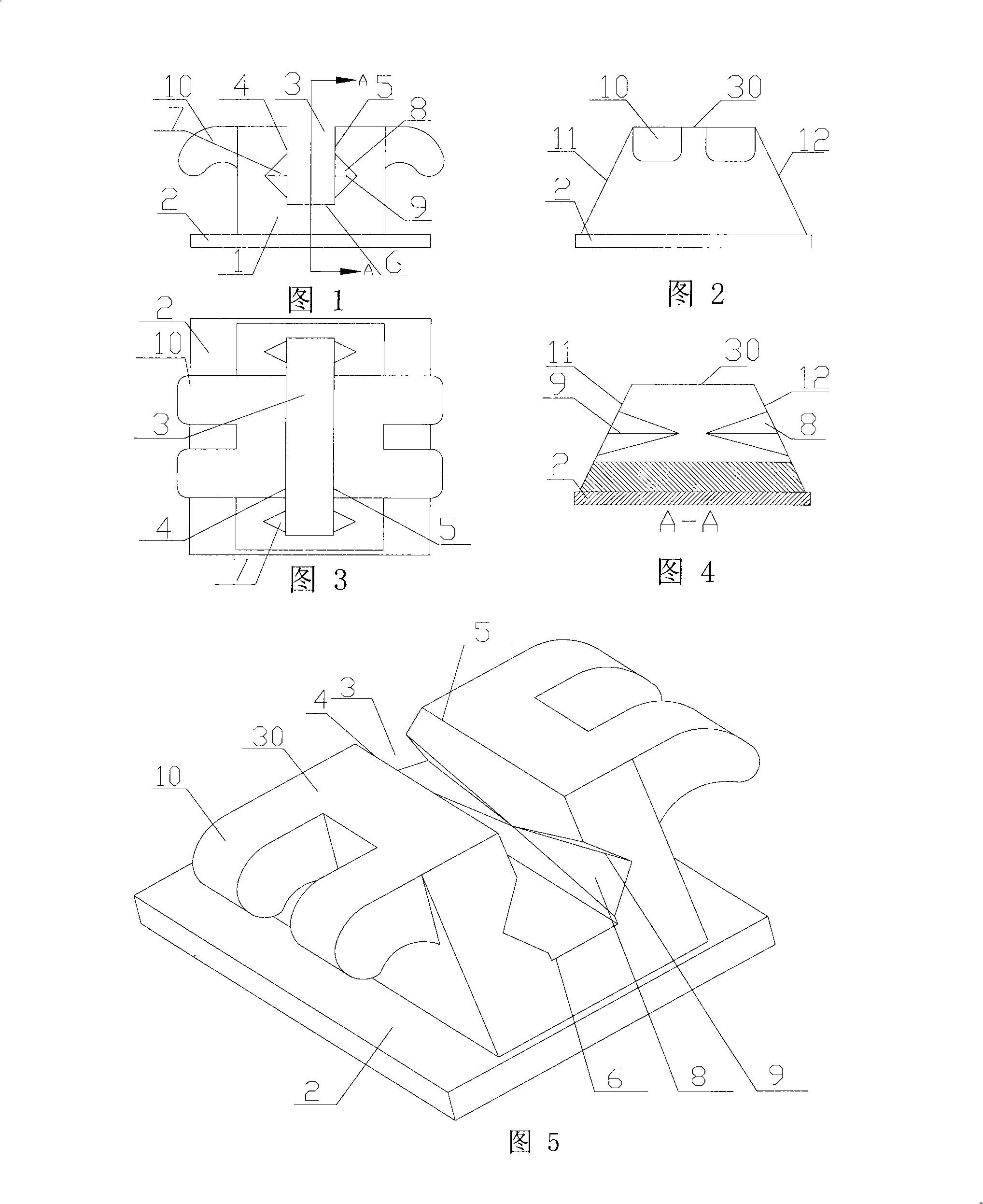
[0075] The present embodiment comprises buccal tube, bracket, dental arch wire and ligation device, with reference to accompanying drawing 1, Fig. 2, Fig. 3, Fig. 4 and Fig. 5, bracket is made of bracket body 1 and base 2 two parts, and base 2. Connected with the surface of the teeth, the bracket body 1 is provided with an archwire groove 3 that penetrates the mesial and distal and opens in the lip-buccal direction. The archwire groove 3 consists of Square side wall 4, gingival side wall 5 and bottom wall 6, the arch wire groove 3 The square side wall 4 and the gingival side wall 5 have auxiliary grooves 7 opening in the archwire groove 3. The auxiliary grooves 7 are in the mesio-distal direction, and four auxiliary grooves 7 start from the The mesial edge 11 and the distal edge 12 of the square side wall 4 and the gingival side wall 5, the buccal-lingual width of the auxiliary groove 7 of the bracket is smaller than the buccal-lingual width of the square arch wire 29 adopt...

Embodiment 2

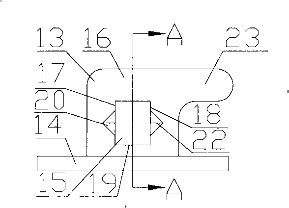
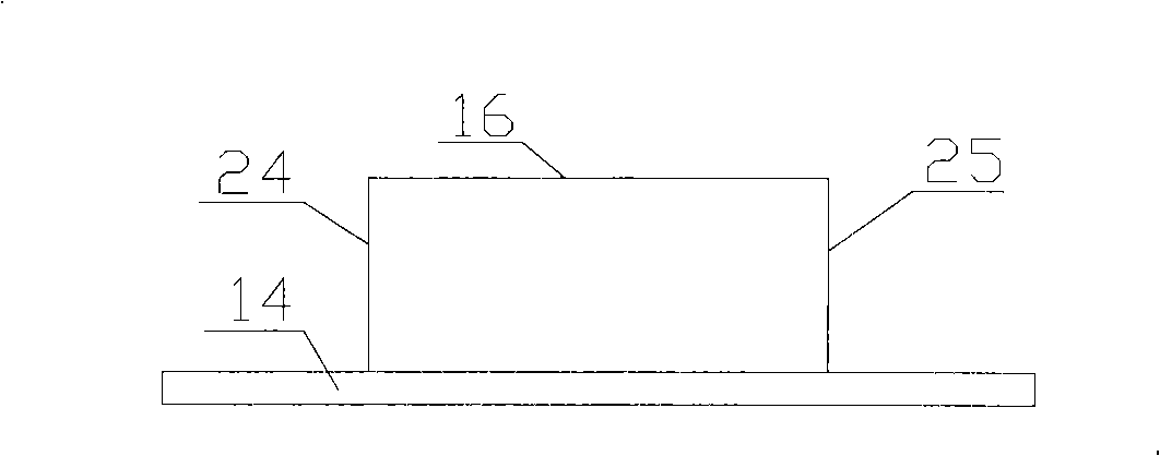
[0079] Referring to accompanying drawings 14, 15, 16, and 17, the difference between this embodiment and embodiment 1 is that there are a pair of ligation wings 10 on the side wall of the archwire slot, located at the top 30 of the side wall of the archwire slot, and the method of use is the same as Example 1.

Embodiment 3

[0081] Referring to accompanying drawings 18, 19, 20 and 21, the difference between this embodiment and embodiment 1 is that there are three pairs of ligation wings 10 on the side wall of the archwire slot, one pair is located in the middle of the top 30 of the side wall, and the other two pairs The ligature wings are respectively located at the mesial and distal of the side wall pre-part 30 , and both protrude outward. At this time, when the bracket is ligated by the pair of ligature wings in the middle, the activity of the arch wire in the arch wire slot is relatively large, and the friction between the arch wire and the bracket is small, which is conducive to the movement of the teeth, and at the same time, the dental arch wire is easy to enter The auxiliary groove 7 on the side wall can allow the teeth to move obliquely. When the two pairs of ligating wings on both sides are used for ligating, the activity of the dental arch wire in the arch wire groove is small, which is c...


PUM


Abstract

The invention relates to a device for correcting teeth, in particular to a carrier-arch-wire combined tooth correcting device. The tooth correcting device which is disclosed by the invention comprises a buccal tube, a carrier groove, a tooth arch wire and a ligation device; wherein, arch wire grooves in the medial-distal direction are arranged on the carrier groove and the buccal tube; auxiliary channels which have openings in the arch wire groove are arranged in the side walls of the arch wire grooves of the carrier groove and the buccal tube; the auxiliary channels are in the medial-distal direction; one or more than one of the auxiliary channels respectively start from the medial edges and / or the distal edges of the square side walls and / or the gum square side walls of the arch wire grooves; the medial edge and the distal edge of the side wall of the arch wire groove form acute angles with the bottom wall; thus the ligated arch wires can move in the arch wire grooves. The positions of the tooth arch wires in the arch wire grooves and the entering-in and the coming-out of the auxiliary channels can be controlled through adopting different arch wires and cooperating different ligation modes, therefore not only a light force can move obliquely the tooth along the medial-distal direction, but also the tooth is easy to be rooted along the buccolingual direction and the medial-distal direction without additional arch wires. Moreover, the carrier-arch-wire combined tooth correcting device has simple structure and convenient use.

Description

technical field [0001] The invention relates to a device for correcting teeth, in particular to a device for correcting teeth combined with a bracket and an arch wire. Background technique [0002] The United States published the patent No. 4877398 on October 31, 1989, which discloses a dental appliance that can use light force to make the teeth move mesially and distally, without the need for external force anchorage and implant anchorage. To strengthen the anchorage, it can quickly and effectively open the deep overburden of the anterior teeth , but in the later stage, it is more troublesome to use additional arch wires for the mesiodistal and buccolingual root control of the teeth. [0003] The mesial side and the distal side of the side wall of the arch wire slot of the commonly used brackets are at right angles to the bottom wall of the arch wire slot, so that the ligature wire will make the dental arch wire near the bottom wall of the arch wire slot Deformation occu...

Claims


Application Information

Patent Timeline
Patent Type & Authority Applications(China)
IPC IPC(8): A61C7/12
CPCA61C7/14
Inventor 宋芝春
Owner 宋芝春
Why Eureka
Try Eureka