
Positioning ring

A positioning ring and fixing plate technology, which is applied in the field of positioning rings, can solve the problems of inconvenient storage and storage of positioning rings, time-consuming and labor-intensive problems, etc.

Inactive Publication Date: 2009-01-21
MITAC PRECISION TECH(KUNSHAN) CORP
View PDF0 Cites 2 Cited by
  • Summary
  • Abstract
  • Description
  • Claims
  • Application Information

AI Technical Summary

Problems solved by technology

If the machines with different types of nozzles are used for mold injection, the positioning ring must be replaced accordingly, which is time-consuming and laborious, and it is very inconvenient to store another temporarily idle positioning ring at the same time.

Method used


Image

  • Positioning ring
  • Positioning ring
  • Positioning ring

Examples


Embodiment Construction

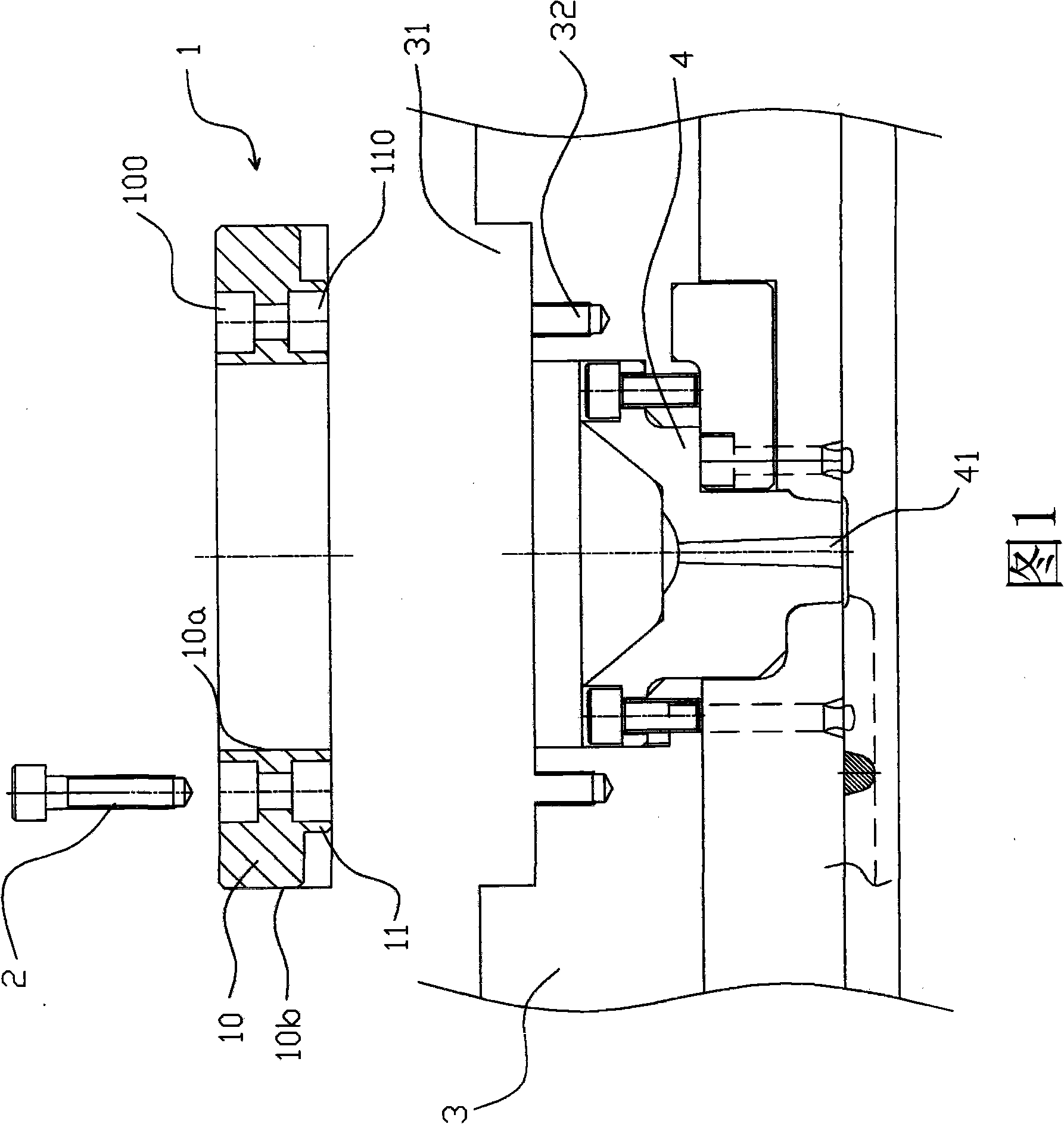
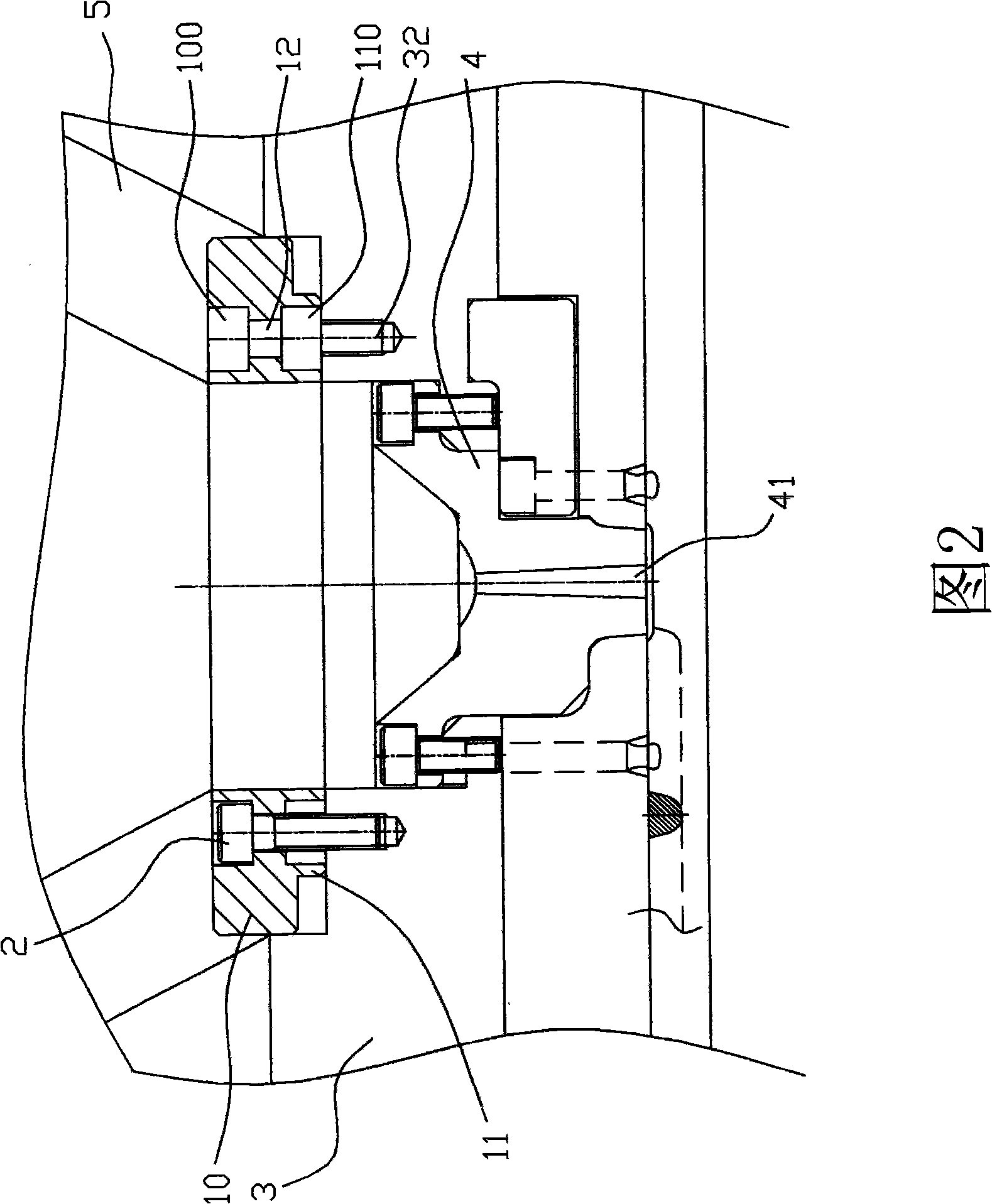
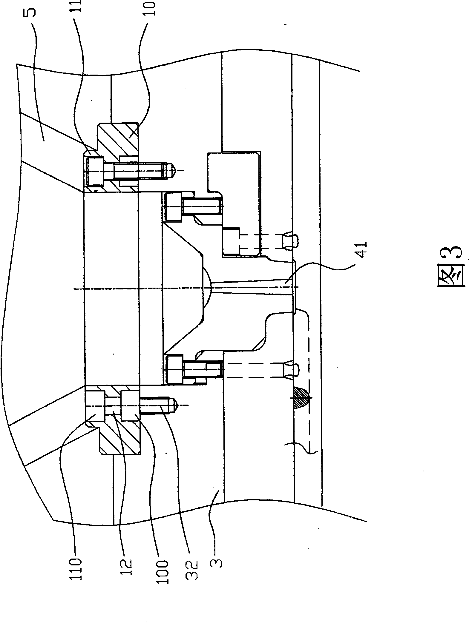
[0010] As shown in Figure 1, it is a cross-sectional view of the present invention when it is separated from the fixed plate, wherein the positioning ring 1 is assembled in a fixed plate 3, and it includes an annular body 10, which includes a concentric inner circle 10a and outer circle 10b, and one side of the main body 10 protrudes along the inner circle 10a, and a protruding body 11 which is also closed and formed into a ring, and the outer diameter of the protruding body 11 is the same as the outer diameter of the main body 10 (that is, the diameter of the outer circle 10b ) inconsistent, in this embodiment, the outer diameter of the protrusion 11 is smaller than the diameter of the outer circle 10b, and the protrusion 11 is provided with at least two first nut holes 110 that are recessed toward the body 10, and the first nut The bottom of the cap hole 110 runs through the body 110 to form at least two holes 12, and at least two second nut holes 100 symmetrical to the first...


PUM


Abstract

The invention discloses a positioning ring that is assembled in a fixing plate and is used for positioning two nozzles of different inner diameters; wherein the positioning ring comprises a body, one side of the body projects and forms a projection, the outer diameter of the projection is less than that of the body, the projection is provided with at least two first nut holes which depress towards the body, the bottom of the first nut holes runs through the body, thus forming at least two holes, the part of the body in the periphery of the holes is provided with at least two second nut holes that are symmetrical with the first nut holes, when a screw is locked and arranged on the fixing plate from one side of the projection or from one side of the body, the nut and the screw rod of the screw are held. When positioning rings of different specifications are needed due to different nozzles and machine stations, only the clamping direction of the positioning ring needs to be changed without delaying work and time, and the storage of the positioning ring is not needed, thus being convenient and rapid.

Description

【Technical field】 [0001] The invention relates to a positioning ring, in particular to a positioning ring capable of positioning machine nozzles with two different inner diameters. 【Background technique】 [0002] In general, the positioning ring is set on the fixed plate to position the machine nozzle above the sprue bushing between the fixed plate and the template, so as to facilitate the injection molding action of the machine nozzle. Currently, the commonly used positioning ring, according to The different nozzle models include at least two specifications: Φ100 (that is, the outer diameter is 100mm) and Φ120 (that is, the outer diameter is 120mm). If the machines with different types of nozzles are used for mold injection, the locating ring must be exchanged accordingly, which is time-consuming and laborious, and it is also very inconvenient to store another temporarily idle locating ring at the same time. [0003] In view of this, it is necessary to provide a positionin...

Claims


Application Information

Patent Timeline
IPC IPC(8): B29C45/17B29C45/26
Inventor 童立夏伟
Owner MITAC PRECISION TECH(KUNSHAN) CORP
Features
  • Generate Ideas
  • Intellectual Property
  • Life Sciences
  • Materials
  • Tech Scout
  • Unparalleled Data Quality
  • Higher Quality Content
  • 60% Fewer Hallucinations
Learn More