Joint structure for quickly connecting corrugated pipe

a corrugated pipe and joint structure technology, applied in the direction of fluid pressure sealing joints, hose connections, mechanical equipment, etc., can solve the problems of easy loosening of the pipe protection, inability to effectively prevent water and ants, and damage to the wire apparatus, so as to increase the benefit of corrugated pipe connection, increase the fixing effect and waterproof effect, and increase the effect of the effect of the effect of the fixing

Active Publication Date: 2008-10-07
CHIU TEH TSUNG
View PDF28 Cites 33 Cited by
  • Summary
  • Abstract
  • Description
  • Claims
  • Application Information

AI Technical Summary

Benefits of technology

[0011]Further, the joint structure can include a washer set on the second screw thread of the main body to increase a locking force of the screw cap.
[0016]Further, an annular flange is formed on the inner bevel of the waterproof tightening ring, and the annular flange can embed in the corrugated pipe so as to increase a fixation effect and a waterproof effect.
[0017]The joint structure according to the embodiment of the present invention has following increased benefits and efficacies. Firstly, the through slot of the clamping claw make the clamping claw has a margin for enlarging an inside diameter thereof. The corrugated pipe with different diameters can directly insert into the clamping claw to increase the advantage of the connection of the corrugated pipe. Secondly, the locking parts of the elastic inner claws can insert in the concave portion of the corrugated pipe, and an end of the locking part of the inner claw corresponding to the corrugated pipe is an oblique guiding surface, thus the corrugated pipe can be easily inserted. Another end of the locking part corresponding to the main body is an erect stopping surface, thus the corrugated pipe cannot be dropped out directly. Therefore, fixity is increased and a loose of the corrugated pipe under pull of outside force can be avoided. Thirdly, the waterproof tightening ring and the annular flange on the inner bevel of the waterproof tightening ring can increase a sealing area. The efficacy of preventing from water, ants and dust can be really achieved.

Problems solved by technology

However, they have different problems as follow.
Therefore, the protecting pipe is easily loosed when an outside force is applied thereto.
Further, a sealing part thereof is only set on a contacting surface between a ring and a main body, the joint structure cannot effectively prevent from water and ants.
Thus, the wire apparatus may be destroyed by damp or ant's gnawing.
Secondly, for example, though Taiwan Patent No. 449169 can quickly assemble and disassemble the protecting pipe, its action is not assured.
At the same time, the joint structure cannot effectively resist a pull of an outside force, and the structure thereof is complicated.
Further, the pressing block is not easy to be machined.
In addition, the joint's action is also not assured.
A loose can be cause by a mistaken touch, and the joint cannot effectively resist a pull of an outside force.
As can be known from the above description, the disclosed or used corrugated-pipe joints have problems of deficient clamping force or bad waterproof capability, separately or together.
At the same time, a problem of inconvenient detachability is further existed.

Method used


Image

  • Joint structure for quickly connecting corrugated pipe
  • Joint structure for quickly connecting corrugated pipe
  • Joint structure for quickly connecting corrugated pipe

Examples


Embodiment Construction

[0028]Reference will now be made to the figures to describe the present invention in detail.

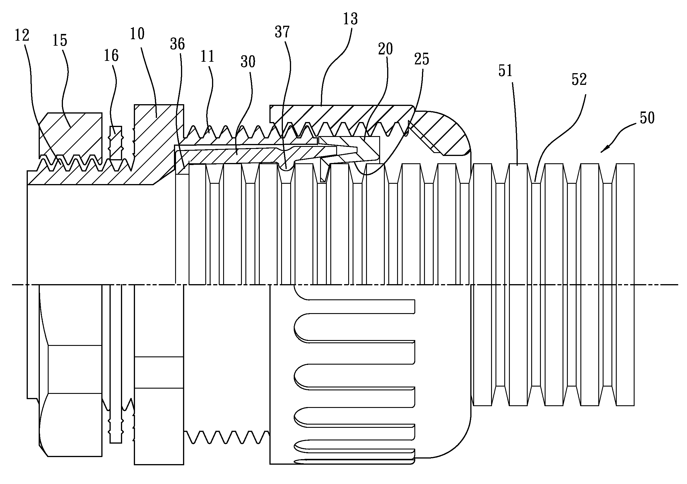
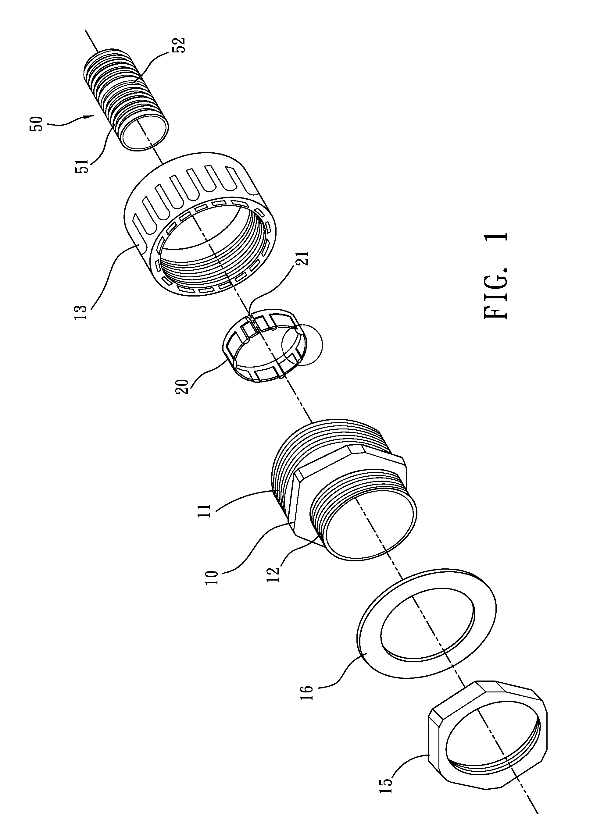
[0029]Referring to FIG. 1, a joint structure according to a first embodiment of the present invention is shown. The joint structure includes a main body 10, a packing screw cap 13, a screw cap 15, and a clamping claw 20. The joint structure is configured for quickly connecting a corrugated pipe 50 and a fixed part. A plurality of bulgy portions 51 and a plurality of concave portions 52 are formed at an out edge of the corrugated pipe. The joint structure can lock the corrugated pipe to the fixed part. Thus, a quick assembling can be achieved, and an efficacy of preventing from water, ants, and dust can further be enhanced.

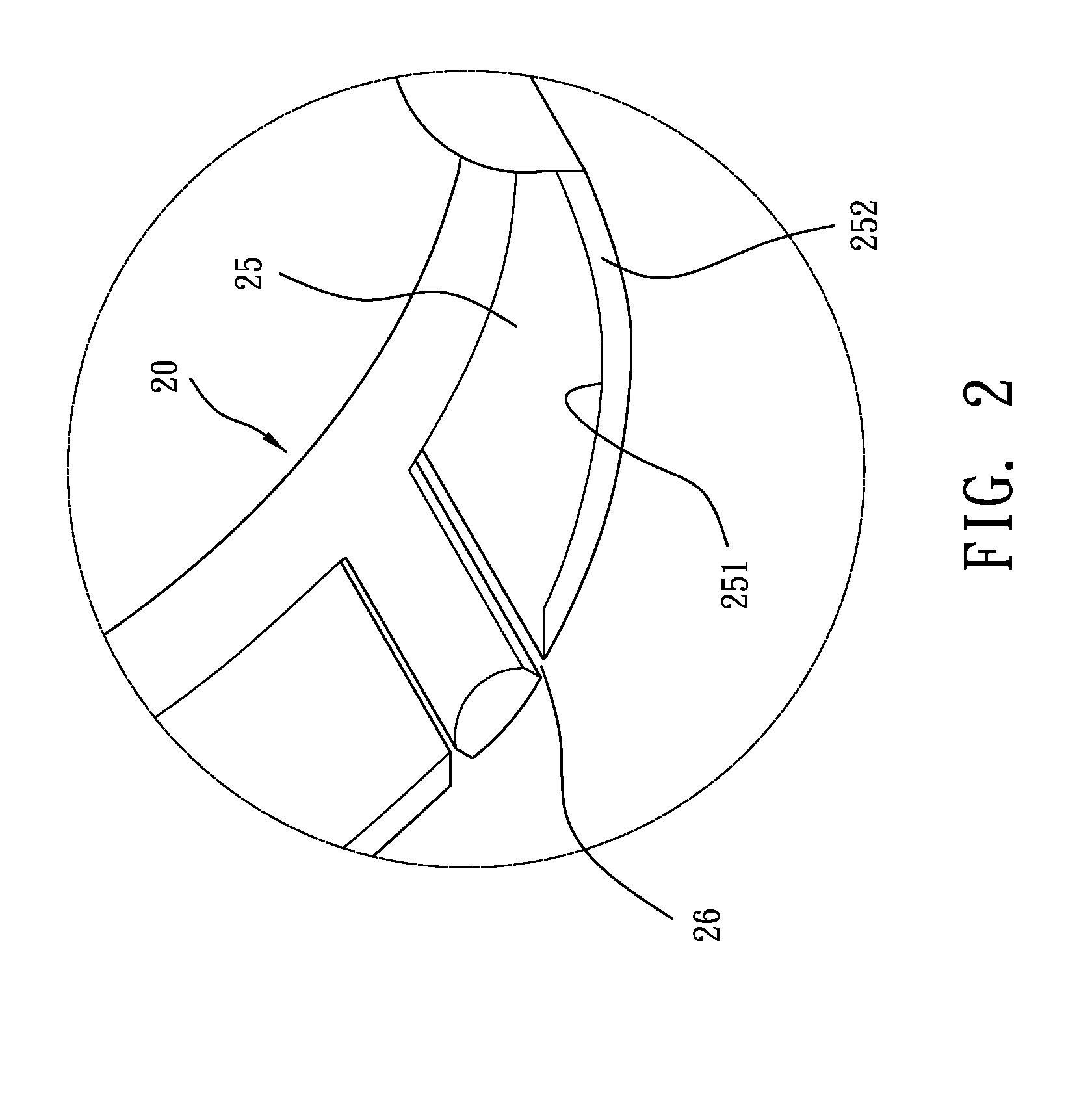
[0030]Referring to FIGS. 1 to 4, a detailed structure of the first embodiment is illustrated. The main body 10 is columnar and hollow. Two ends of the main body 10 form a first screw thread 11 and a second screw thread 12, respectively. The first screw thread 11 is configure...


PUM


Abstract

A joint structure for connecting a corrugated pipe to a fixed part includes a main body, a packing screw cap, and a clamping claw. The clamping claw is sandwiched between the main body and the packing screw cap. The clamping claw defines a through slot at an edge thereof to make the clamping claw can enlarge an inside diameter thereof. A plurality of inner claws is formed at the edge of the clamping claw. A locking part protruding towards the center of the clamping claw is formed at an end of each of the inner claws. Two slits are respectively defined at two sides of each inner claw so that the inner claw has elasticity. The corrugated pipe with different diameters can directly insert into the clamping claw from outside, and the corrugated pipe cannot be dropped out directly.

Description

BACKGROUND[0001]1. Field of the Invention[0002]The present invention relates to a field of corrugated-pipe jointing technology and, more particularly, to a joint structure for quickly connecting a corrugated pipe. The joint structure can make an inside diameter of its clamping claw generate a margin, so that the corrugated pipe with different diameters can directly insert into the clamping claw from outside.[0003]2. Description of the Prior Art[0004]A corrugated pipe is a kind of hollow pipe for protecting a cable from damage caused by entering of foreign matter such as percolating water, ants, dust, and so on. In order to follow a bend and distortion of the cable during its disposing, and to increase an agility and retractility of the corrugated pipe, annular bulgy portions and annular concave portions are alternately formed at an out edge of the corrugated pipe. Generally, when the cable needs to be inserted into a fixed part, a corrugated-pipe joint can be used for fixing the cor...

Claims


Application Information

Patent Timeline
Patent Type & Authority Patents(United States)
IPC IPC(8): F16L11/118F16L25/02H02G3/18
CPCF16L25/0036H02G3/0691
Inventor CHIU, TEH-TSUNG
Owner CHIU TEH TSUNG
Why Eureka
Try Eureka