Container cap

a container cap and cap body technology, applied in the field of container caps, can solve the problem of not allowing anyone to take out the plunger, and achieve the effect of reducing pressure, more versatility, and more snug fi

Active Publication Date: 2014-04-15
GACERS LLC
View PDF10 Cites 32 Cited by
  • Summary
  • Abstract
  • Description
  • Claims
  • Application Information

AI Technical Summary

Benefits of technology

[0008]The body of the invention can be inserted into a neck or attached to any type of container that holds a substance. The body has slight indentations, flanges, hinge flashes mechanisms or areas “flashes” that are more concentrated with materials at the base not to allow the plunger to fall into a container with the flanges / flashes staying attached to the body. The areas of concentrations for the flashes are close enough together so that when activated the plunger portion the plunger goes through the bottom past the end of the last area on the bottom of the cutting portion chamber area to allow full distribution of the ingredients not having the attached, now opened, bottom interfering with the ingredients that are being dispensed. The body can also have on the outside areas on the sides slightly indented areas running up and down preferably to allow air to escape while inserting the invention into a container thus allowing other reduction of pressure when adding the invention. The rim area that is stationed on the lip area can be solid so the product inside is forced to flow through upwards through the bottom of the body through the holes in the plunger. There can also be a variety of one or more holes / open areas around the surface to allow additional flow rate if necessary. Flashes can also be attached at certain angles from the lip to the body to allow the invention to be more versatile in different neck sizes to have a more snug fit to reduce or minimize movement of the invention in the container it is placed in. The body has opposite rings as the plunger located in the start position and the finished activated position. One or more of the seal rings can have a barb like angle thus not allowing the plunger to be able for anyone to take out. The body can also be molded in it's shape or any shape at any location in a container itself thus eliminating an expense of one piece and then having the plunger added after it is filled or not filled with desired product for use. Also at any location of a container there can be just an opening with a flat surface, tread or snap so that the invention can be placed in and ready for use, this also can be ultrasonically welded. The invention can also have treads on the body of the invention to enable the product to be screwed on a container. It also can have snap rings with a pull of safety ring, can be attached directly to a can-pouch-bottle-syringe-IV instruments / bags and any other type of container product. The body chamber of the invention when inserted into a neck of a container when resting on the neck or clicked into the neck can either have flow holes around the top of the rim or no holes and allow the product once activated to flow through the one or more holes in the plunger mechanism. The bottom of the chamber can have a line of weakening with flanges / flashes so after the invention has been manually activated the bottom portion can stay attached to the body. The bottom can also be open and after filled with product can have any type seal attached including desiccant imbedded or adhered to secure the products freshness until ready to use.

Problems solved by technology

One or more of the seal rings can have a barb like angle thus not allowing the plunger to be able for anyone to take out.

Method used


Image

  • Container cap
  • Container cap
  • Container cap

Examples


Embodiment Construction

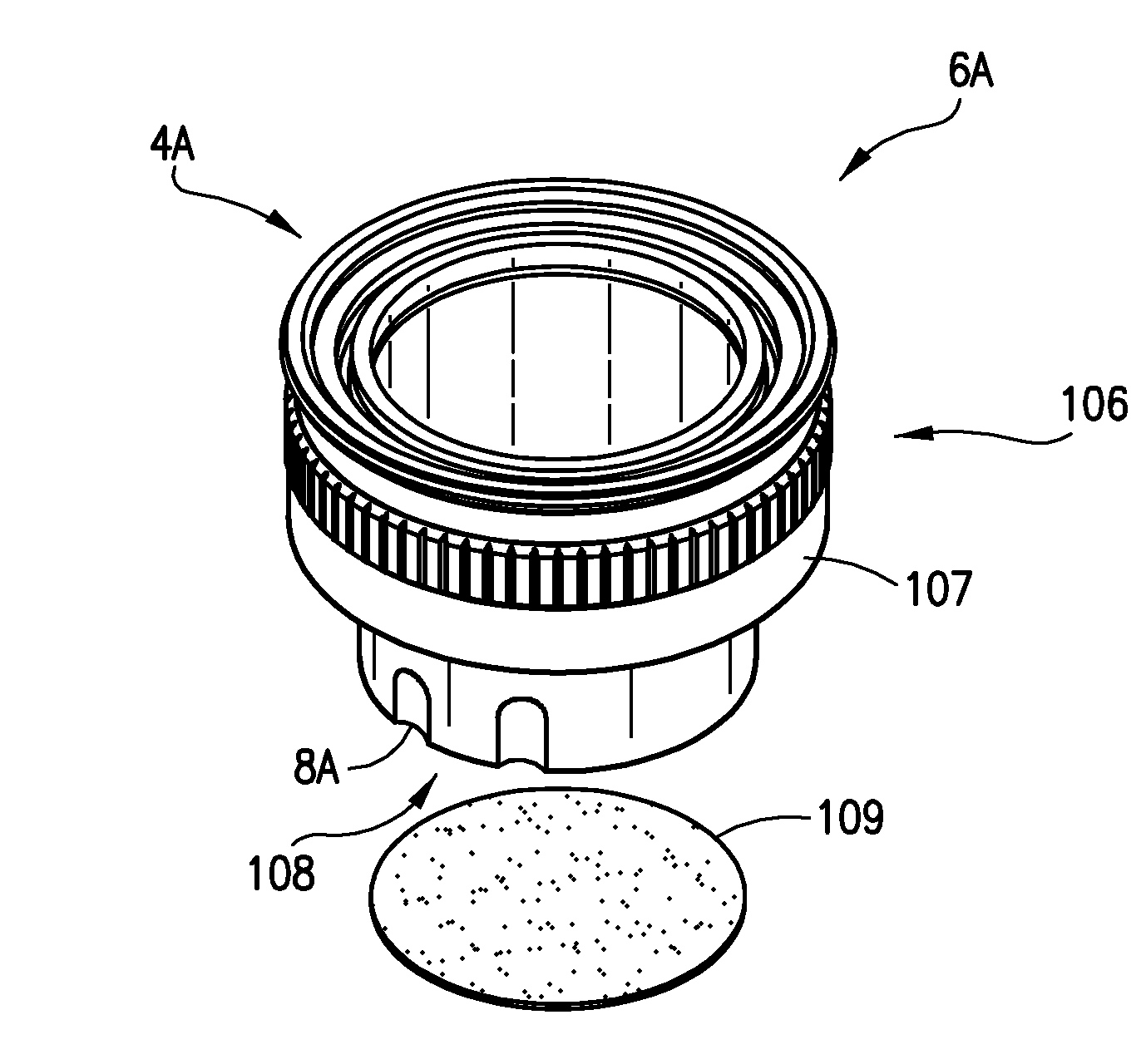
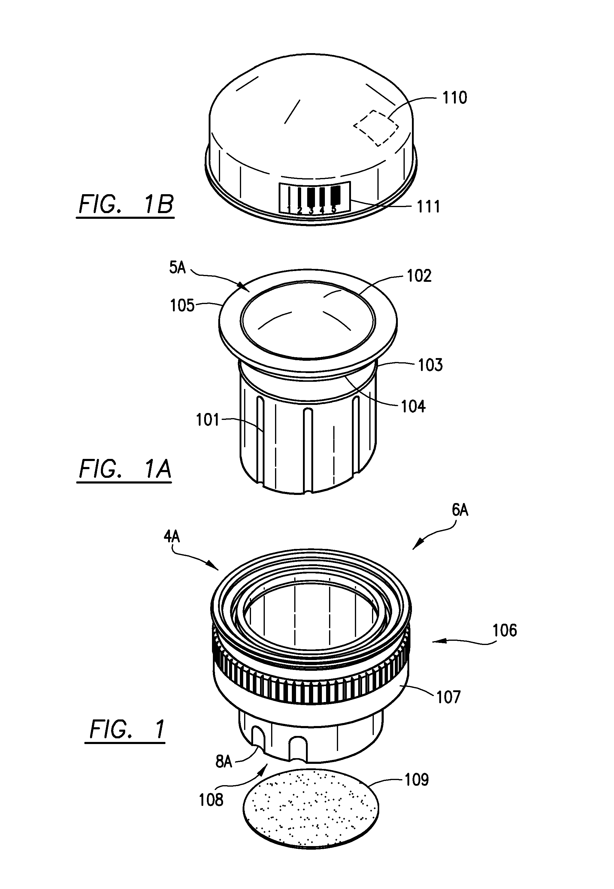
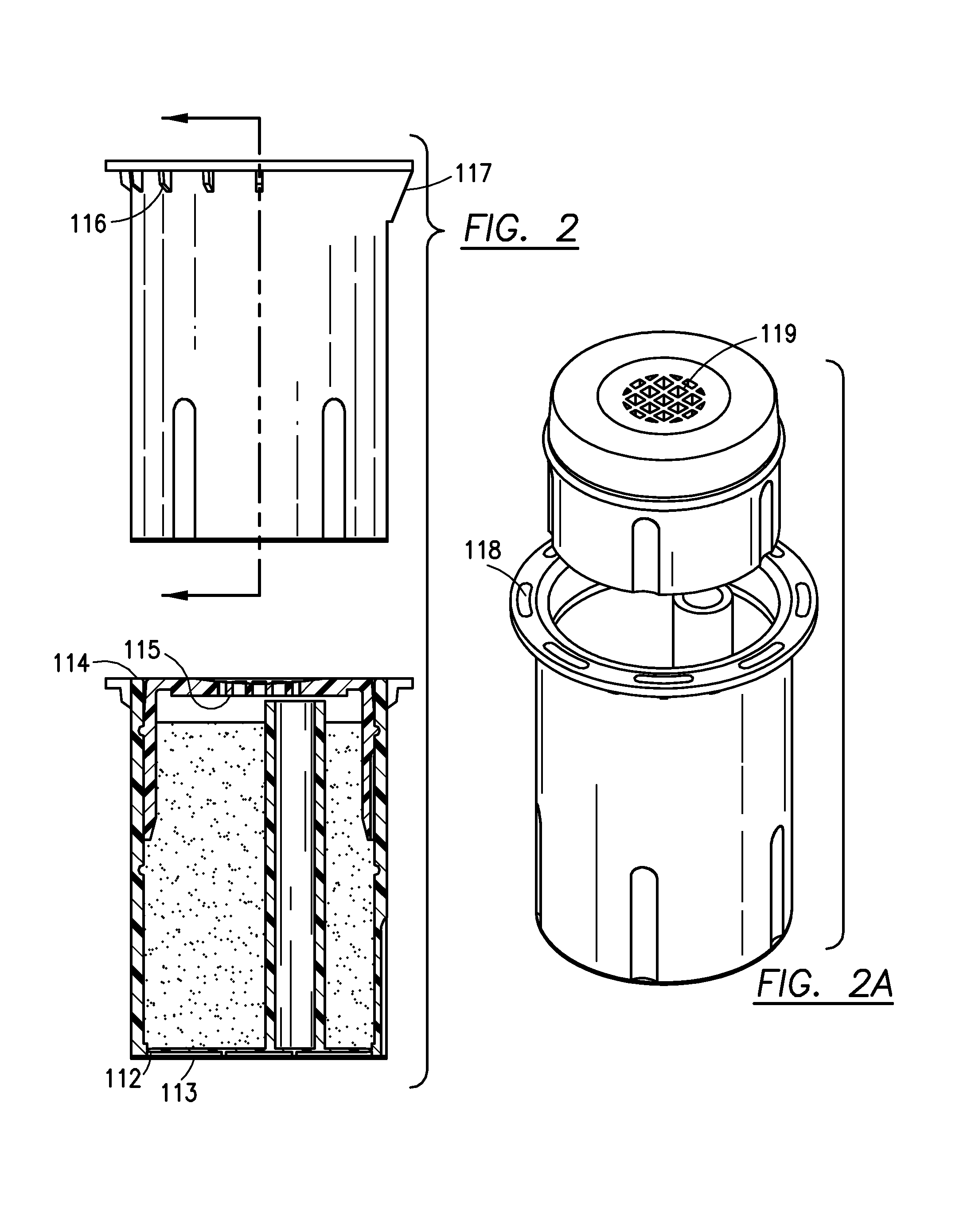
[0037]The plunger mechanism can have a multitude of designs but the preferred embodiment is with one or more holes on the top of the plunger mechanism with either smooth or slightly raised surface areas to allow flow of product after activation and also a safety seal that preferable has one or more absorbents added to it for moisture absorbent to allow the product inside to remain fresher and then to allow flow of the products after mixing together. The plunger can have raised surface areas around the holes used for flowing of the product, around the outside of the plunger mechanism and also around the body so a seal-preferably with an absorbent material added to the seal for moisture absorbent to keep the product secure until ready to use. The invention also has one or more seal rings located on the sides of the plunger that can be of different widths with a reverse fit on the body to allow a click in type seal fit to allow the ingredients inside more stability and to have a very s...


PUM


Abstract

A cap dispensing chamber to hold powder and/or liquids in a contained unit with a line of weakening, including but not limited to for bottles, pouches, cartons, cans, drums, IV bags, syringes, and any other type of container that can hold a product. The body and the plunger fits snugly with one another allowing ingredients to be stored and activated by an individual when on a as needed basis. A dust cover for allowing RFID, Nano and barcodes that can be applied during or post manufacturing or any location on or in the invention A body can be molded with a screw cap, snap lid, click-in, or by itself that can ultimately fit on any type or style container.

Description

BACKGROUND OF THE INVENTION[0001]1. Field of the Invention[0002]A threaded, snapped, sealed or non threaded cap that can have one or more ingredients in the cap with a one or more chambers to hold liquid and or powder to be able to dispense ingredients when ready to use a product for freshness and to be able to have one or more ingredients to allow mixing of ingredients at time of use.[0003]2. Description of Related Art[0004]Normally all liquids are formulated and made knowing that the concern is shelf life and chemical reaction between different ingredients. This invention allows a product to be formulated for effectiveness rather than what has to be formulated. It also allows less toxic and material to be used in containers do to the ingredients be stored in the invention until time of use thus allowing as an example hot fill containers to be eliminated in beverage drinks and now being able to use cold fill containers using less material and chemicals for a product.SUMMARY OF THE ...

Claims


Application Information

Patent Timeline
Patent Type & Authority Patents(United States)
IPC IPC(8): B65D25/08
CPCB65D51/2871B65D51/285B65D2251/009B65D25/08B65D2203/10B65D51/2835B65D2251/0015B65D51/18
Inventor ANDERSON, MICHAEL, R.
Owner GACERS LLC
Why Eureka
Try Eureka