
Automatic transfer switch electric appliance for AC/DC mixing device

An automatic transfer switch, AC and DC hybrid technology, applied in the direction of electric switches, circuits, electrical components, etc., can solve the problems that AC and DC cannot be connected at the same time, and the switching between AC power and DC power cannot be realized, so as to improve the arc extinguishing effect, Conducive to promotion and application of a wide range of effects

Inactive Publication Date: 2009-01-21
深圳市泰永科技股份有限公司
View PDF0 Cites 7 Cited by
  • Summary
  • Abstract
  • Description
  • Claims
  • Application Information

AI Technical Summary

Problems solved by technology

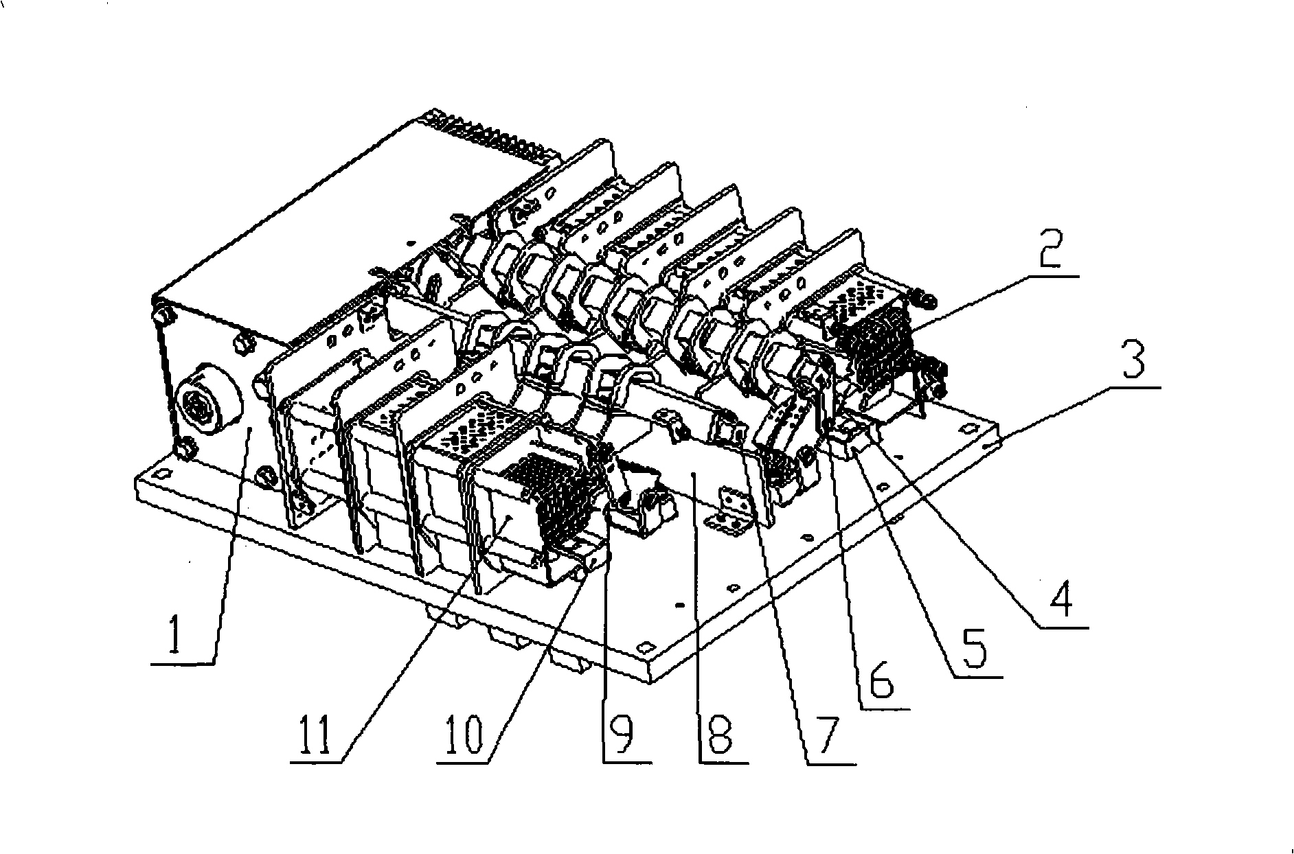
[0004] The purpose of the present invention is to provide an automatic transfer switch for an AC / DC hybrid device, which has two independent transfer systems, which can respectively connect and disconnect the AC power supply and the DC power supply, and ensure that the AC and DC cannot be connected at the same time. The conversion of the load between the AC power supply and the DC power supply overcomes the deficiency that the existing automatic transfer switch cannot switch between the AC power supply and the DC power supply during the conversion process

Method used


Image

  • Automatic transfer switch electric appliance for AC/DC mixing device
  • Automatic transfer switch electric appliance for AC/DC mixing device
  • Automatic transfer switch electric appliance for AC/DC mixing device

Examples


Embodiment Construction

[0018] Below in conjunction with accompanying drawing, the present invention is described in further detail with preferred embodiment:

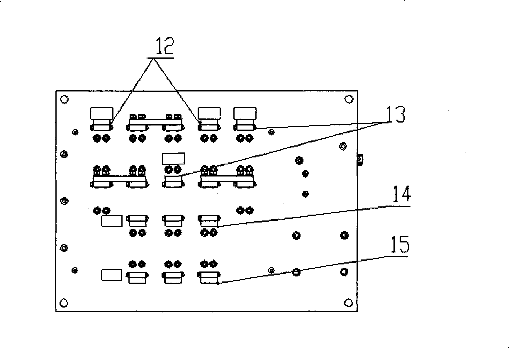
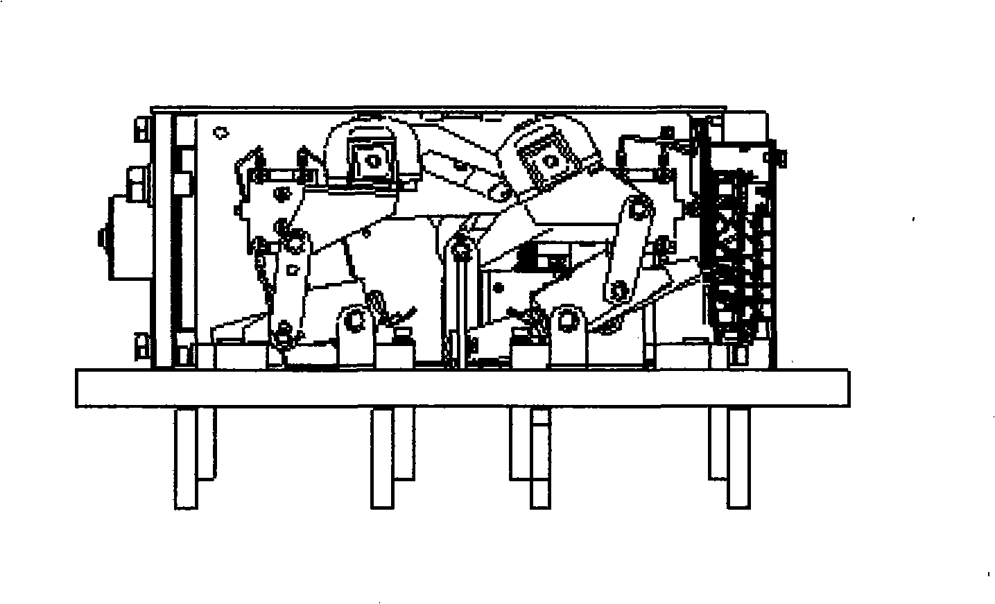
[0019] The present invention consists of a base plate (3), a main control part (1), an arc extinguishing device A (2) and an arc extinguishing device B (11), an input terminal (14) on the AC side, a main shaft (7) on the AC side, an AC side The moving contact (9) of the AC side, the output terminal (15) of the AC side, the static contact (10) of the AC side, the input terminal (12) of the DC side, the main shaft (6) of the DC side, the moving contact of the DC side (4), the output terminal (13) on the DC side, the static contact (5) on the DC side and the insulating plate (8), the main control part (1), the switch part on the AC side, and the switch part on the DC side are all fixed on the bottom plate (3), the switch parts of the AC and DC sides are arranged on both sides of the bottom plate to ensure sufficient electrical clearance, and the...


PUM


Abstract

The invention relates to an automatic transfer switching equipment of the alternating-current / direct-current mixing apparatus, which aims at solving the problem that the switching process of an existing automatic change-over switch can not realize the switching between the alternating current main and the direct current main. The equipment is composed of a bottom board, a master control part, arc-extinguishing equipments A and B, and an input terminal a main shaft, a movable contact, an output terminal and a fixing contact of the alternating-current side,, an input terminal, a main shaft, a movable contact, an output terminal, a fixing contact and an insulating plate of the direct-current side, wherein the master control part, a switch part of the alternating-current and a switch part of the direct-current side are fixed on the bottom board, and the switch parts of the alternating-current side and the direct-current side are separated by an insulation plate. The automatic transfer switching equipment has two sets of independent transfer systems, which can respectively switch on and broke the alternating current main and the direct current main, when one of the common power supply and the stand-by power supply of a user is the direct current power supply and the other is the alternating power supply, the switching between the two power supplies can be realized through using the same change-over switch, and the invention has the advantages the application range is wide, the operation and use is convenient and flexible, and the automatic transfer switching equipment is beneficial for the spread.

Description

technical field [0001] The invention relates to the field of electrical switches, in particular to an automatic transfer switching appliance of an AC / DC hybrid device. Background technique [0002] Existing automatic transfer switching appliances on the market generally have two power supply input terminals and one power supply output terminal. This type of automatic transfer switch can only be used to switch between two power sources of the same nature, that is, an AC switch is used when the two power sources are AC, and a DC switch is used when the two power sources are DC. [0003] In practical applications, there are many places where electricity is used. One of the common power sources and the backup power source is AC power, while the other is DC power. It is necessary to have an automatic transfer switch with an AC-DC hybrid device that can operate on AC power. Converts power to and from DC power. Contents of the invention [0004] The purpose of the present inven...

Claims


Application Information

Patent Timeline
IPC IPC(8): H01H9/24
Inventor 黄正乾曾舟王光岩
Owner 深圳市泰永科技股份有限公司
Learn More