
Communication device for a railway vehicle

A technology for railway vehicles and equipment, which is applied in the fields of railway signals, railway car body components, railway signals and safety, and can solve problems such as high signal-to-noise ratio, complexity, and reduced link signal-to-noise ratio, and achieve convenient maintenance work and materials The effect of reducing the amount and reducing the installation stress

Active Publication Date: 2013-04-24
ALSTOM TRANSPORT TECH SAS +1
View PDF1 Cites 0 Cited by
  • Summary
  • Abstract
  • Description
  • Claims
  • Application Information

AI Technical Summary

Problems solved by technology

However, train antennas usually only receive a single electric field component in a particular spatial direction and therefore only present a portion of the energy emitted by the waveguide, leaving the rest of the radiated portion unused
Therefore, this reduces the signal-to-noise ratio of the link, which in turn limits the effective output for ground-to-train communication, however, in modern ground-to-train communication systems, the signal-to-noise ratio should be relatively high
Moreover, the propagation of multiple transmission modes may occur simultaneously in the waveguide, and signal jitter and local attenuation may occur between these transmission modes. Therefore, it is necessary to use a sandwich waveguide structure as a mode filter. Considering the material used in the railway environment It is complicated to make such a device from materials that are acceptable in terms of durability or the possibility of toxic fumes being emitted in the event of a fire

Method used

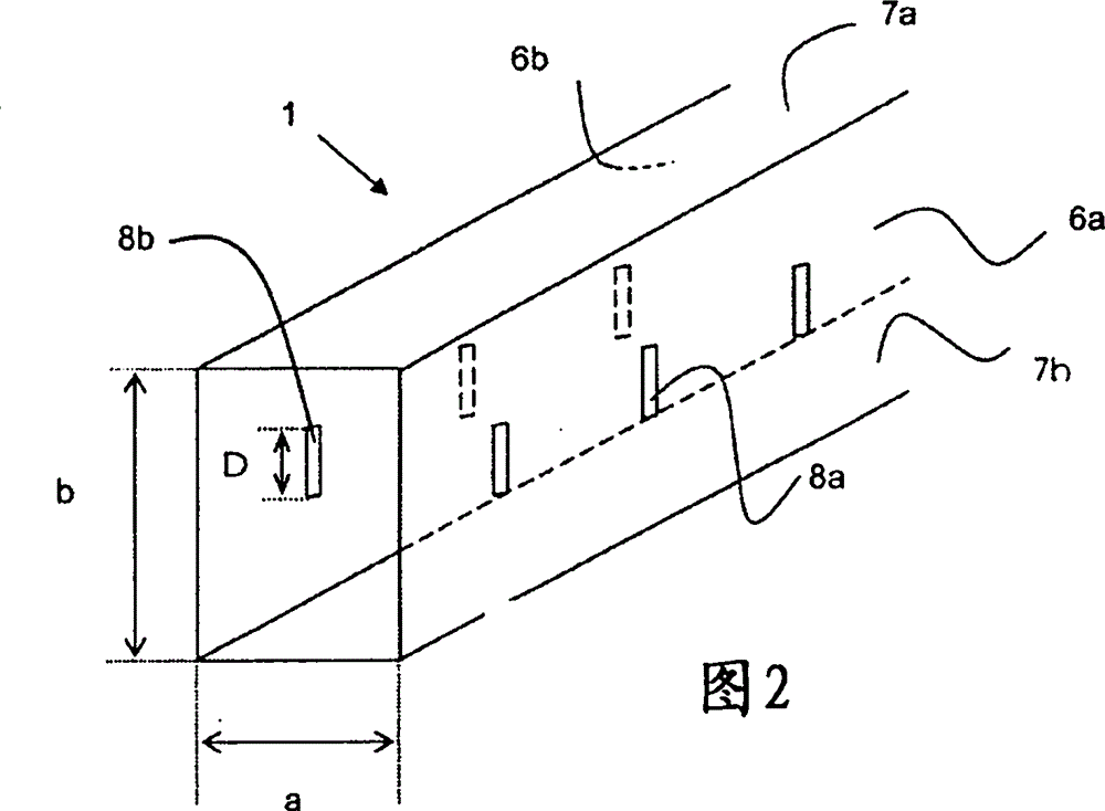
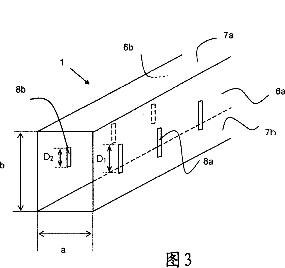

Image

  • Communication device for a railway vehicle
  • Communication device for a railway vehicle
  • Communication device for a railway vehicle

Examples


Embodiment Construction

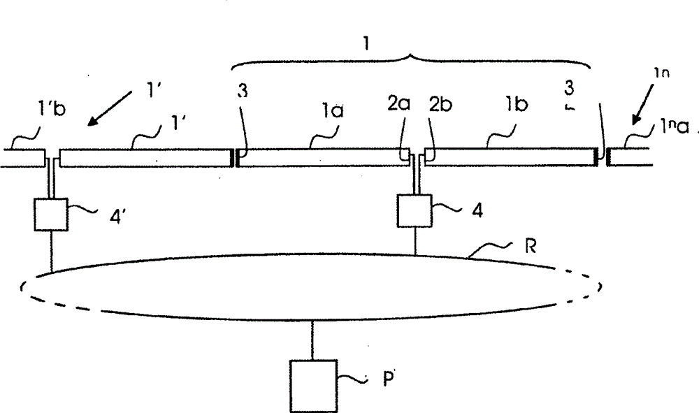
[0032] attached figure 1 A device for communication between a control station P and at least one vehicle A running on a track is shown, comprising a plurality of fixed waveguides 1, 1', 1 n And so on, placed consecutively one after the other along the track. The length of the communication equipment depends on the type of network. The length of the waveguides is hundreds of meters and the communication device contains n waveguides covering the entire railway network.

[0033] Since all waveguides are identical, only waveguide 1 will be described. The waveguide 1 is made up of two separate parts 1a and 1b into which waves are injected at the ends 2a and 2b of the parts 1a and 1b, for example by means of a coaxial line-waveguide conversion. The ends 3a and 3b of the waveguide 1 are charged to avoid the establishment of a standing wave in the waveguide, for example by means of waveguide-to-coaxial conversion and a suitable resistive charge, or on the metal short-circuit surfac...


PUM


Abstract

The device has a waveguide (1) parallel to a track and provided with two emissive faces (6a, 6a) respectively pierced with two arrays of slots (8a, 8b) that respectively pass electromagnetic radiations in microwave frequency wavelengths. One emissive face of the waveguide is opposite to the other emissive face. A powering unit provides power to the waveguide, and a reception unit receives microwaves originating from the waveguide.

Description

technical field [0001] Broadly, the present invention relates to an apparatus for communicating between one or more railway vehicles and a control station, and more particularly to a radiating waveguide continuous communication apparatus. Background technique [0002] From the applicant's document FR 2 608 119, a device for continuous communication between a railway vehicle and a control station is known, which has a waveguide radiating in the main mode, also called TE 01 mold. The device consists of a hollow tube parallel to the transport track, and the hollow tube is placed along the track to form a waveguide whose only one emitting face is penetrated by a network of asymmetrically shaped openings for Allows microwave electromagnetic radiation to pass through. The network of these openings (hereinafter referred to as "slots" due to their narrow and elongated shape) can itself be placed so that its emitting face is at a relatively close angle to the antenna on the vehicle...

Claims


Application Information

Patent Timeline
Patent Type & Authority Patents(China)
IPC IPC(8): B61L3/22B61L23/22
CPCB61L3/227H01Q1/3225
Inventor M·海德伯特D·杜霍特
Owner ALSTOM TRANSPORT TECH SAS
Learn More