Intake air noise adjuster
A technology of adjusting device and changing device, applied in the direction of intake muffler, etc., can solve problems such as increase of intake sound
- Summary
- Abstract
- Description
- Claims
- Application Information
AI Technical Summary
Problems solved by technology
Method used
Image
Examples
no. 1 Embodiment approach
[0030] (structure)
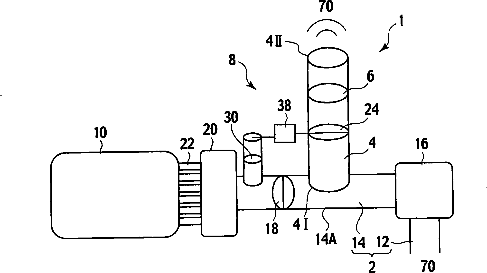
[0031] figure 1 A conceptual diagram showing the overall configuration of the intake air sound adjustment device 1 according to the first embodiment of the present invention. However, figure 1 It is also applicable to the second, third and fourth embodiments which will be described later.
[0032] like figure 1 As shown, the intake sound adjustment device 1 of the first embodiment is installed on the intake pipe 2 (also referred to as "intake passage 2"), and the intake sound adjustment device 1 includes a communication pipe 4, an elastic body 6 and a flow Road area changing device 8.
[0033] First, the intake duct 2 and components related to the intake duct 2 will be described.
[0034] The intake duct 2 serves as an intake passage from the outside air 70 to the engine 10 , and it includes a dust-side intake duct 12 and a clean-side intake duct 14 .
[0035] A first open end of the dust-side intake duct 12 is connected to the air cleaner 16 , and a...
no. 2 approach
[0155] (structure)
[0156] Hereinafter, a second embodiment of the present invention will be described.
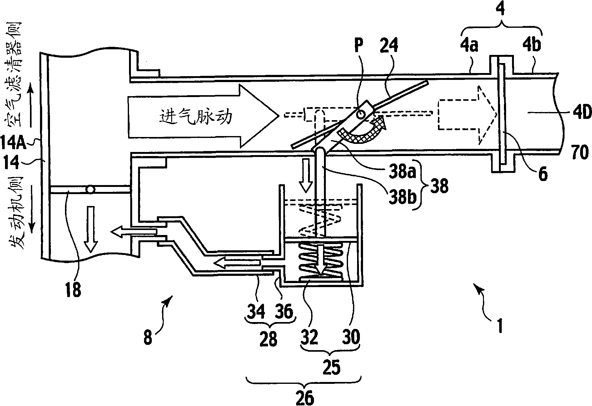
[0157] Figure 4 and Figure 5 The configuration of the intake air sound adjustment device 1 according to the second embodiment of the present invention is shown respectively.
[0158] Figure 4 shows the state of the flow path area changing device 8 during slow acceleration or idling, while Figure 5 The state of the flow path area changing device 8 during rapid acceleration is shown.
[0159] like Figure 4 and Figure 5 As shown, the configuration of the intake sound adjustment device 1 according to the second embodiment is substantially the same as that of the intake sound adjustment device 1 according to the first embodiment, except for the configuration of the flow path area changing device 8 . Therefore, a detailed description of the structure of components other than the flow path area changing device 8 is omitted.
[0160] The channel area changing device...
no. 3 approach
[0214] (structure)
[0215] Hereinafter, a third embodiment of the present invention will be described.
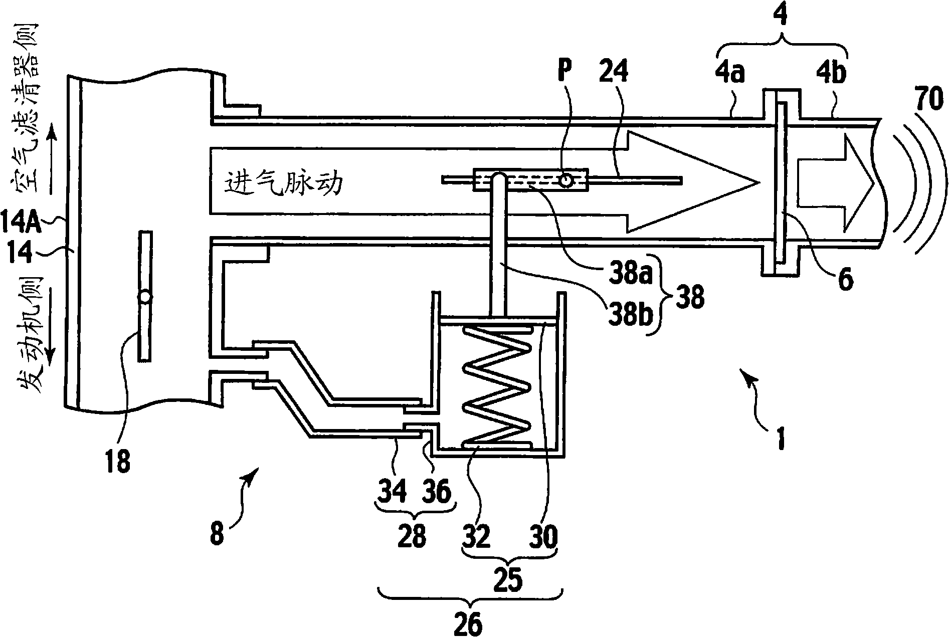
[0216] Image 6 and Figure 7 The configuration of the intake sound adjustment device 1 according to the third embodiment of the present invention is shown respectively. Image 6 shows the state of the flow path area changing device 8 during slow acceleration or idling, while Figure 7 The state of the flow path area changing device 8 during rapid acceleration is shown.
[0217] like Image 6 and Figure 7 As shown, the configuration of the intake sound adjustment device 1 according to the third embodiment is substantially the same as that of the intake sound adjustment device 1 according to the first embodiment, except for the configuration of the flow path area changing device 8 . Therefore, a detailed description of the structure of members other than the flow path area changing device 8 will be omitted.
[0218] The intake sound adjustment device 1 of the third ...
PUM
 Abstract
Description
Claims
Application Information
 - R&D
- Intellectual Property
- Life Sciences
- Materials
- Tech Scout
- Unparalleled Data Quality
- Higher Quality Content
- 60% Fewer Hallucinations
Browse by: Latest US Patents, China's latest patents, Technical Efficacy Thesaurus, Application Domain, Technology Topic, Popular Technical Reports.
© 2025 PatSnap. All rights reserved.Legal|Privacy policy|Modern Slavery Act Transparency Statement|Sitemap|About US| Contact US: help@patsnap.com


