Mechanical type linear reciprocating synchronizing device

A linear reciprocating and synchronous device technology, applied in the direction of conveyor objects, transportation and packaging, etc., can solve the problems of low heavy load accuracy, small load capacity, and synchronous motion lag, so as to ensure motion synchronization accuracy, improve production efficiency, and synchronize Sexually precise effects

Active Publication Date: 2015-05-13
KUSN FASTEC MACHINERY
View PDF6 Cites 0 Cited by
  • Summary
  • Abstract
  • Description
  • Claims
  • Application Information

AI Technical Summary

Problems solved by technology

[0004] 1. The load capacity is small and the rigidity is low. In the case of heavy load, the actuator such as servo motor or stepper motor is prone to hysteresis or step loss, that is, the heavy load accuracy is low;
[0005] 2. During high-speed motion, the lag of synchronous motion becomes more obvious
[0006] 3. The motion characteristics are poor, and it is easy to generate shock and vibration. Most of the motion controllers now control the displacement, speed and acceleration of a motion axis, while the jerk characteristic (jerk) that characterizes the motion characteristics of shock and vibration is rarely controlled. , which makes the shock and vibration obvious during high-speed motion. On the other hand, due to the lag of motion, the motion controller needs to perform an interpolation operation after executing one or more control cycles to correct the motion deviation. The correction needs to be realized by changing the magnitude and direction of the force or torque, and the change of this force or torque also makes the dynamics of synchronous motion worse

Method used


Image

  • Mechanical type linear reciprocating synchronizing device

Examples


Embodiment Construction

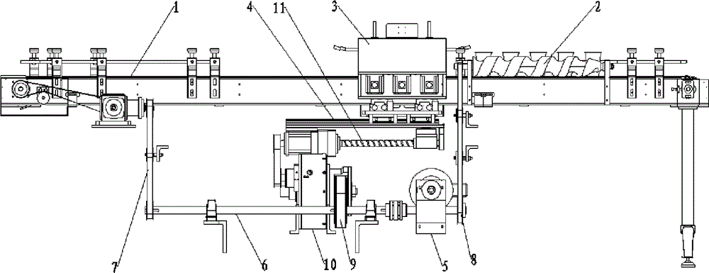
[0012] Embodiment: a kind of mechanical linear reciprocating synchronizing device, comprises conveyor belt 1, separating screw rod 2, manipulator 3 and linear guide rail 4, and separating screw rod 2 can be rotatably positioned on one end of conveyor belt 1, and separating screw rod 2 axially along conveyor belt 1 Placed in the direction of movement, the manipulator 3 can be slidably positioned on the linear guide rail 4, and the linear guide rail 4 is fixed on one side of the width direction of the conveyor belt 1, and is also provided with a motor 5, a main drive shaft 6, a first, a second, a third transmission device 7, 8, 9, the cam mechanism 10, the power output of the motor 5 to the main drive shaft 6, the first, second, and third transmission devices 7, 8, 9 respectively transmit the power of the main drive shaft 6 to the driving roller and the separating screw of the conveyor belt 1 2 and the cam device, the cam mechanism 10 drives the manipulator 3 to slide along the l...


PUM


Abstract

The invention discloses a mechanical type linear reciprocating synchronizing device. A separation bolt can be rotationally located at one end of a conveying belt and is axially placed along the moving direction of the conveying belt, a mechanical arm can be located on a linear guide rail in a sliding mode, and the linear guide rail is fixed at one side of the width direction of the conveying belt. The mechanical type linear reciprocating synchronizing device is further provided with a motor, a main driving shaft, a first transmission device, a second transmission device, a third transmission device and a cam mechanism. Motive power of the motor is output to the main driving shaft, the first transmission device, the second transmission device and the third transmission device respectively enable motive power of the main driving shaft to be transmitted to a driving roller of the conveying belt, the separation bolt and the cam mechanism, and the cam mechanism drives the mechanism arm to slide along the linear guide rail. The mechanical type linear reciprocating synchronizing device is large in power, strong in rigidity, and accurate in synchronism. During high-speed movement, the whole device can keep a mute effect, avoids shock and impact caused by heavy load and the high-speed movement, responds quickly, and improves production efficiency of a production line.

Description

technical field [0001] The invention relates to a linear reciprocating device, in particular to a mechanical linear reciprocating synchronization device. Background technique [0002] On the production line, the manipulator often needs to do reciprocating linear motion to operate the products on the conveyor belt. At the same time, the feeding device must keep synchronous feeding with the manipulator and the conveyor belt. Currently, the motion controller is commonly used to control the conveyor belt, manipulator and feeding device. Synchronous action, this kind of synchronous control method uses the electronic gear and electronic cam function of the motion controller to realize the control of motion parameters such as displacement, speed, acceleration and so on between the motion axes, and then realizes synchronous action; [0003] This control method has the following disadvantages: [0004] 1. The load capacity is small and the rigidity is low. In the case of heavy load,...

Claims


Application Information

Patent Timeline
Patent Type & Authority Patents(China)
IPC IPC(8): B65G47/74B65G47/90
Inventor 唐照山
Owner KUSN FASTEC MACHINERY
Why Eureka
Try Eureka