Motor fan pump for vacuum cleaner

A technology of vacuum cleaners and air pumps, which is applied in the direction of vacuum cleaners, machines/engines, pumps, etc., which can solve the problems of high noise of vacuum cleaners and achieve the effect of ensuring quiet performance

Active Publication Date: 2019-05-10
苏州市海朋生活家电有限公司
View PDF6 Cites 0 Cited by
  • Summary
  • Abstract
  • Description
  • Claims
  • Application Information

AI Technical Summary

Problems solved by technology

If we unilaterally pursue strong suction and blindly increase the power of the motor, the result is that the produced vacuum cleaner is too noisy, and the user will not only be complained by others, but even the user himself cannot bear the excessive noise.

Method used


Image

  • Motor fan pump for vacuum cleaner
  • Motor fan pump for vacuum cleaner

Examples


Embodiment 1

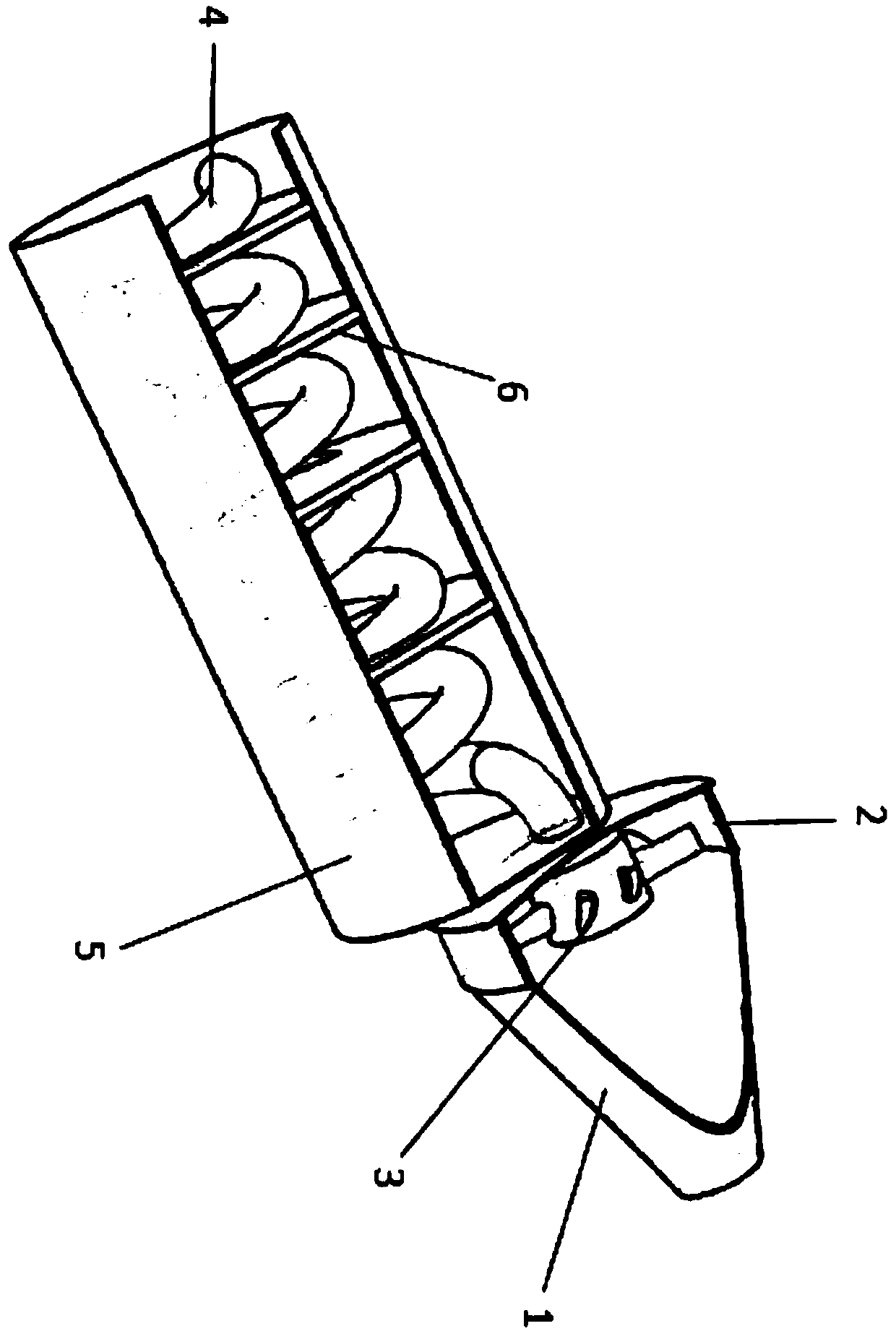
[0032] Such as figure 1 As shown, a motor air pump for a vacuum cleaner includes: an air intake pipe 1, which is a circular frustum shell structure, the top of the air intake pipe 1 is provided with a first opening, and the bottom of the air intake pipe 1 is provided with a second opening Fan housing 2, which is a cylindrical shell structure, the top opening of the fan housing 2 is airtightly connected with the second opening of the air intake duct 1, and the bottom of the fan housing 2 is provided with a third opening; the fan 3 is installed on In the blower cover 2, the blower fan 3 discharges air toward the third opening, and the blower fan 3 is connected with the inner wall of the blower blower cover 2 through a fixing frame; The air duct 4 is provided with a fully covered exhaust hood 5, the first end of the exhaust hood 5 is closed, the first end of the exhaust duct 4 runs through the first end of the exhaust hood 5 and is connected to the fan. The third opening of the ...

Embodiment 2

[0042] The wall of the exhaust pipe 4 in the buffer chamber where the second end of the exhaust cover 5 is located does not have the through hole.

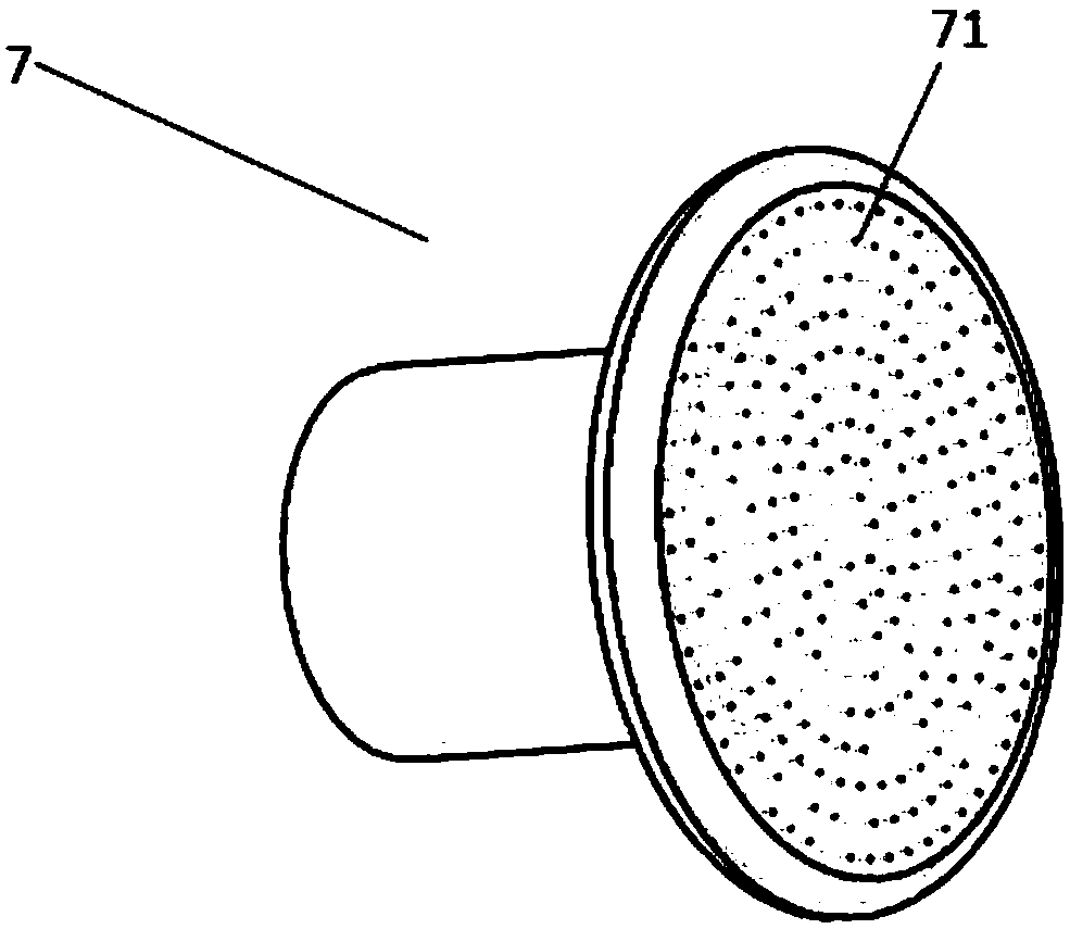
[0043] Such as figure 2 As shown, the exhaust pipe 4 also includes a small hole muffler 7, the air inlet of the small hole muffler 7 is connected through the tail of the exhaust pipe 4, and the center distance between adjacent small holes 71 on the small hole muffler It is more than 5 times the diameter of the small hole 71. The buffer cavity where the second end of the exhaust cover 5 is located is the tail end buffer cavity through which the airflow finally flows. Will be completely discharged from the tail of the exhaust pipe 4. By connecting a small hole muffler 7 at the tail of the exhaust pipe 4, the mid-low frequency noise retained in the airflow is converted into a high-frequency sound inaudible to the human ear, thereby achieving the purpose of noise reduction. When the distance between the small holes 71 is large eno...


PUM


Abstract

The invention discloses a motor air pump for a dust collector. The motor air pump comprises an air inlet pipeline, a fan outer cover, a fan and an exhaust pipeline, wherein a first opening is formed in the top of the air inlet pipeline; a second opening is formed in the bottom of the air inlet pipeline; a third opening is formed in the bottom of the fan outer cover; the fan outputs air towards the third opening; a main body of the exhaust pipeline is of a spiral structure; a fully enclosing exhaust hood is arranged outside the exhaust pipeline; a first end of the exhaust hood is closed; a first end of the exhaust pipeline penetrates through the first end of the exhaust hood and is connected with a third opening of the fan outer cover in a closed mode; a second end of the exhaust hood is open; the internal space of the exhaust hood is divided into a plurality of closed buffer cavities through partition plates; a second end of the exhaust pipeline sequentially penetrates through the partition plates and is drawn out of a second end of the exhaust hood; and a plurality of evenly formed through holes are formed in the pipeline wall, in the exhaust hood, of the exhaust pipeline. The noise of the air pump of the dust collector can be effectively lowered.

Description

technical field [0001] The invention relates to the field of vacuum cleaners, in particular to a motor air pump for a vacuum cleaner. Background technique [0002] Since the invention of the vacuum cleaner, its noise has always been an old problem that plagues people. There are two main sources of noise. One is that after the vacuum cleaner generates negative air pressure, the air is sucked in. During the rapid flow of air, sound waves are continuously generated by compression, expansion, and collision with the body. The second is the mechanical vibration caused by the rotation of the motor in the vacuum cleaner. Sound waves that travel through air. [0003] In order to obtain more powerful suction, the power requirements of the vacuum cleaner will be greater, and the corresponding noise problem will also increase accordingly. If we unilaterally pursue strong suction and blindly increase the power of the motor, the result is that the produced vacuum cleaner is too noisy, a...

Claims


Application Information

Patent Timeline
Patent Type & Authority Patents(China)
IPC IPC(8): F04D29/66F04D29/52A47L5/06
CPCA47L5/06F04D29/522F04D29/663F04D29/664
Inventor 陆苏忠
Owner 苏州市海朋生活家电有限公司
Why Eureka
Try Eureka