Air conditioning device
A technology of air-conditioning device and decompression device, which is applied in the direction of space heating and ventilation, heating method, lighting and heating equipment, etc., and can solve the problems of reduced quietness of repeaters
- Summary
- Abstract
- Description
- Claims
- Application Information
AI Technical Summary
Problems solved by technology
Method used
Image
Examples
Embodiment approach 1
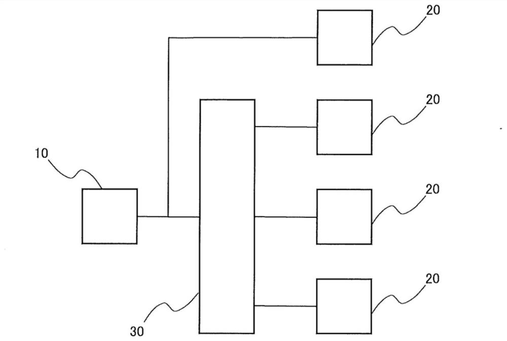
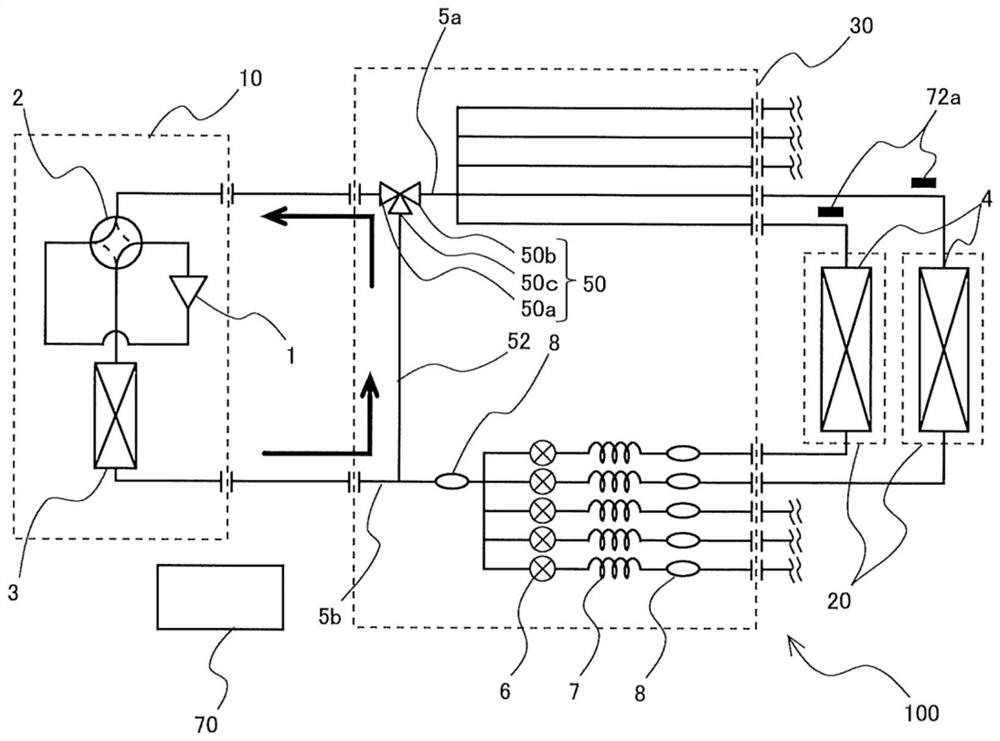
[0022] The air conditioner 100 according to Embodiment 1 will be described. figure 1 It is a schematic diagram showing an example of the air conditioner 100 according to the first embodiment. figure 2 yes means figure 1 A simplified refrigerant circuit diagram of a part of the air conditioner 100 of FIG. In addition, in the following drawings, the dimensional relationship and shape of each component may differ from actual ones. In addition, in the following drawings, the same reference numerals are assigned to the same members or parts or members or parts having the same functions, or the reference numerals are omitted.
[0023] like figure 1 As shown, the air conditioner 100 includes an outdoor unit 10 , a plurality of indoor units 20 , and a relay unit 30 . The outdoor unit 10 and the relay unit 30 are connected by refrigerant piping. Also, some of the plurality of indoor units 20 are connected to the outdoor unit 10 via the relay unit 30 , and the other part of the pl...
Embodiment approach 2
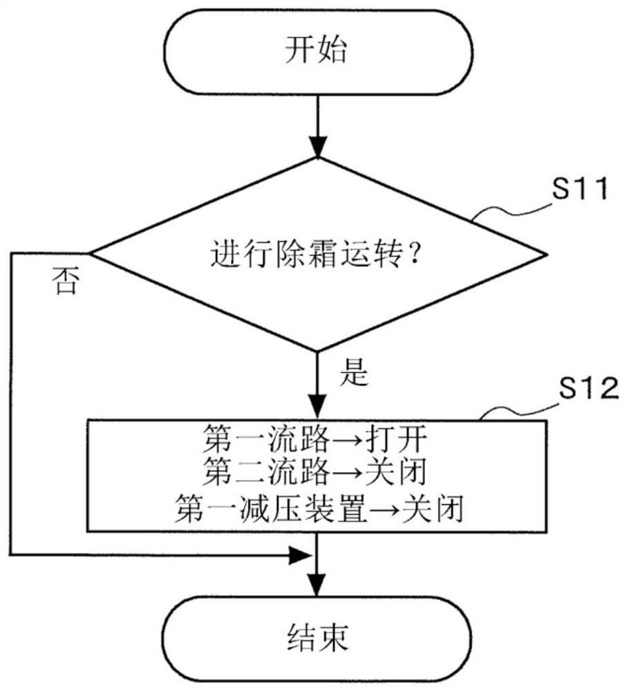
[0063] In Embodiment 2, using Figure 4 The control processing of the flow path switching valve 50 and the first decompression device 6 during the oil recovery operation will be described. Figure 4 It is a flowchart showing control processing of the flow path switching valve 50 and the first decompression device 6 during the oil recovery operation in the second embodiment. The configuration of the air conditioner 100 is the same as that of Embodiment 1, and thus description thereof will be omitted.
[0064] Here, the “oil recovery operation” refers to an operation mode of the air conditioner 100 in which the compressor 1 recovers the lubricating oil discharged together with the refrigerant into the compressor 1 . When the cooling operation is performed for a long time with a low load, the lubricating oil discharged from the compressor 1 together with the refrigerant remains in the refrigerant piping connecting the outdoor unit 10 and the relay unit 30 , especially on the hea...
Embodiment approach 3
[0071] use Figure 5 The configuration of the air conditioner 100 according to Embodiment 3 will be described. Figure 5 It is a simplified refrigerant circuit diagram showing an example of the refrigerant circuit of the air-conditioning apparatus 100 according to the third embodiment. In the air conditioner 100 according to Embodiment 3, the indoor unit 20 is provided with a refrigerant leakage detection device 74 . The control device 70 receives refrigerant leakage detection information from the refrigerant leakage detection device 74 . As the refrigerant leakage detection device 74, for example, a refrigerant leakage detection sensor is provided. As the refrigerant leak detection sensor, for example, a gas sensor such as a semiconductor gas sensor, a hot wire semiconductor gas sensor, or an infrared gas sensor is used. In addition, the refrigerant leakage detection sensor may be an oxygen concentration type gas sensor that detects a drop in oxygen concentration, or may b...
PUM
 Abstract
Description
Claims
Application Information
 - R&D
- Intellectual Property
- Life Sciences
- Materials
- Tech Scout
- Unparalleled Data Quality
- Higher Quality Content
- 60% Fewer Hallucinations
Browse by: Latest US Patents, China's latest patents, Technical Efficacy Thesaurus, Application Domain, Technology Topic, Popular Technical Reports.
© 2025 PatSnap. All rights reserved.Legal|Privacy policy|Modern Slavery Act Transparency Statement|Sitemap|About US| Contact US: help@patsnap.com


