Method and system for automatically recovering maintenance and control of optical communication apparatus remotely

A maintenance control and equipment maintenance technology, applied in the field of optical communication, can solve the problems of service board DCC byte disconnection, network management disconnection, and failure to send commands to cancel maintenance control, etc., and achieve the effect of restoring remote network management control

Inactive Publication Date: 2011-06-22
ZTE CORP
View PDF0 Cites 0 Cited by
  • Summary
  • Abstract
  • Description
  • Claims
  • Application Information

AI Technical Summary

Problems solved by technology

Since the control commands of the network management to the remote optical communication equipment are transmitted through the DCC bytes in the overhead, the above maintenance control commands may often cause the DCC bytes of the service boards to fail, and the DCC bytes of the service boards to fail will cause the network management The disconnection leads to the inability to issue the command to cancel the maintenance control. At this time, the cancellation of the maintenance control command requires the DCC byte communication, and the DCC byte communication needs to cancel the maintenance control command. The two fall into a dead loop. As a result, services and network management control cannot be restored remotely.
[0003] At present, the device handles this problem by reducing the maintenance control that may lead to the disconnection of optical communication equipment, such as inserting alarms, inserting error codes, and setting loopbacks. Port-level operations are not supported, but obviously this method cannot completely avoid the above problems. , while also reducing the functionality of maintenance control commands

Method used


Image

  • Method and system for automatically recovering maintenance and control of optical communication apparatus remotely
  • Method and system for automatically recovering maintenance and control of optical communication apparatus remotely
  • Method and system for automatically recovering maintenance and control of optical communication apparatus remotely

Examples


Embodiment 1

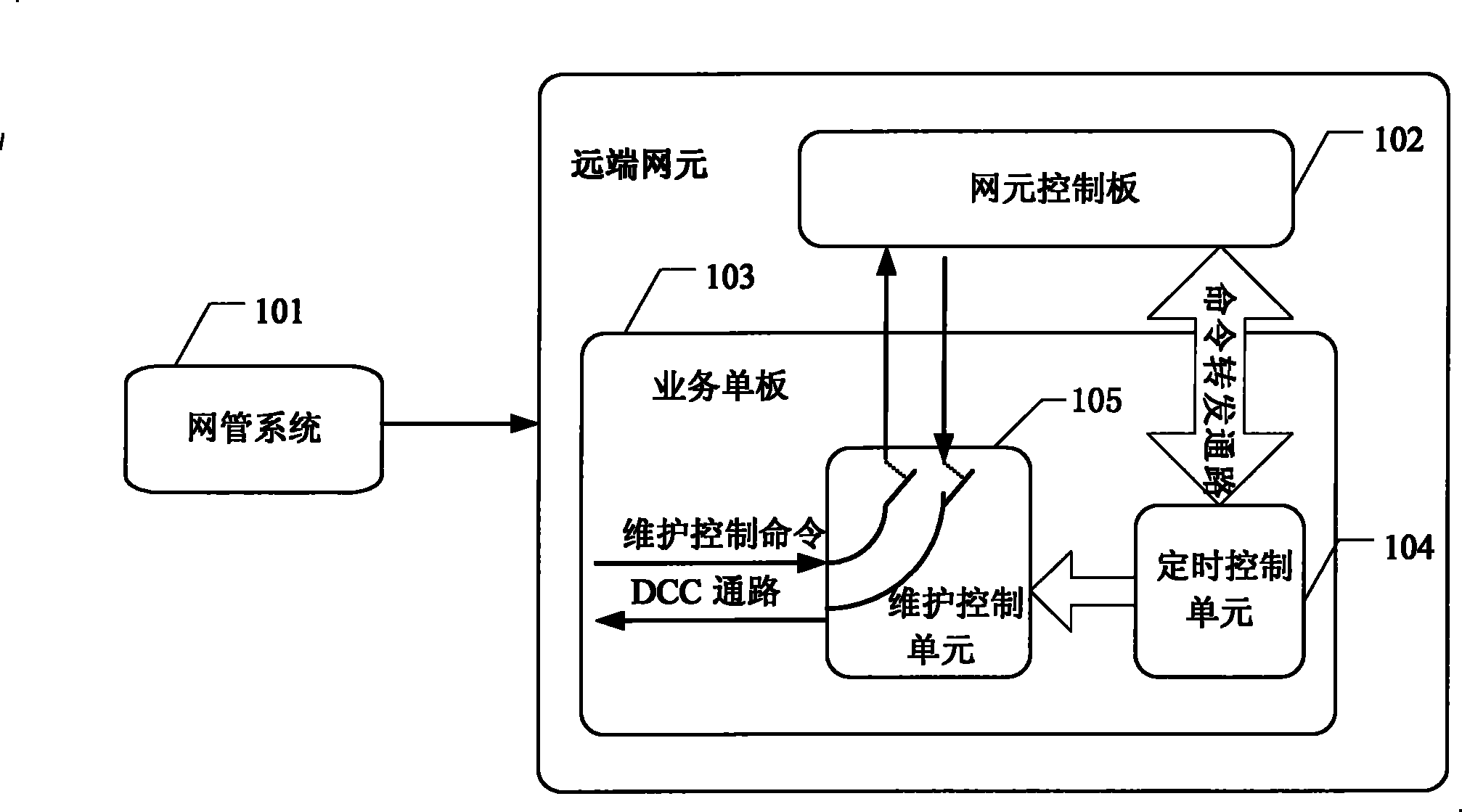
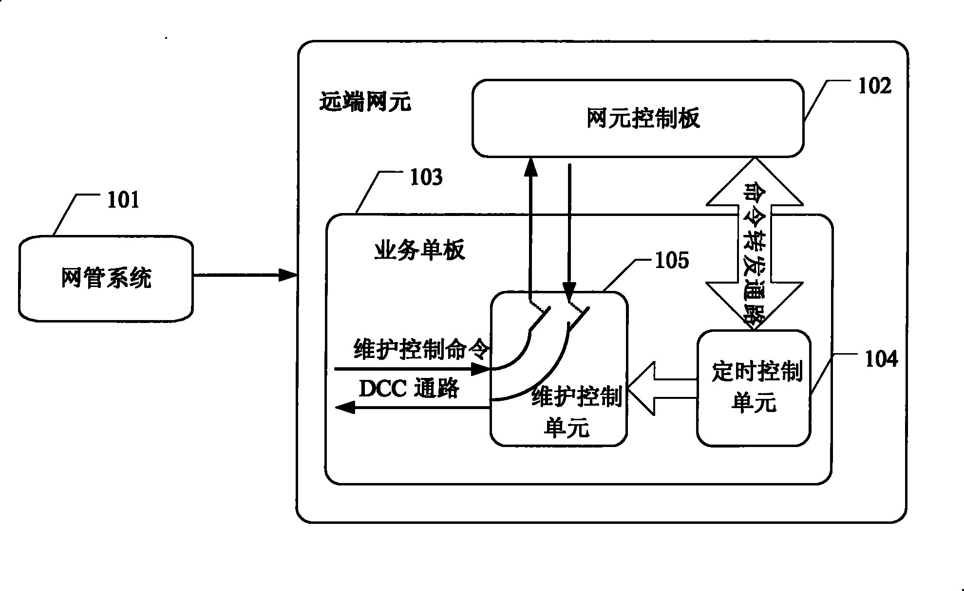
[0035] The following takes the optical interface service board on the SDH network element equipment as an example to describe the specific implementation steps in detail:

[0036] Step 1: The network management adds a timing control setting interface for alarm insertion, error code insertion, loopback setting, and laser control setting;

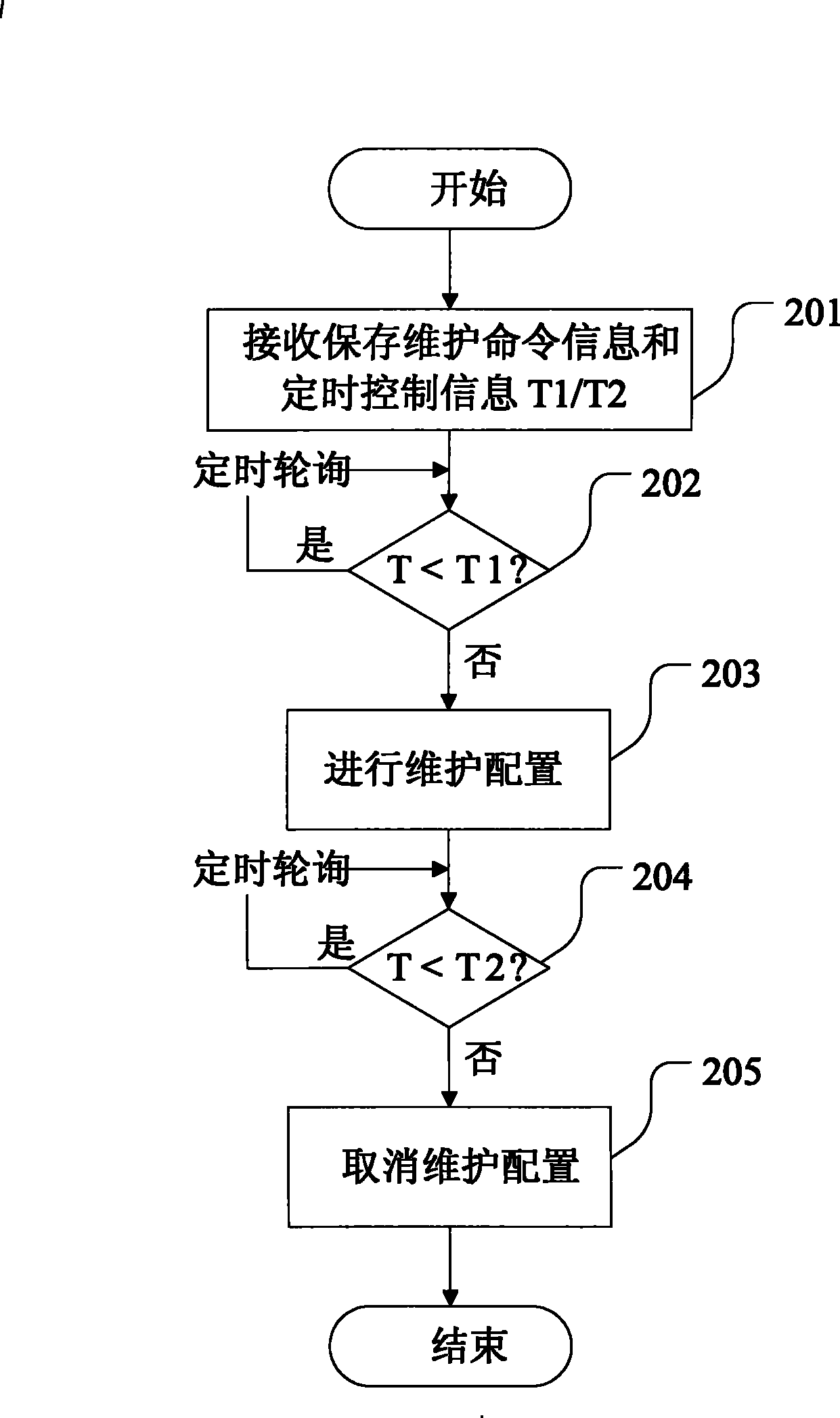
[0037] Step 2: Add a timing control unit to the service board. After receiving the alarm insertion, error code insertion, loopback setting, and laser control timing maintenance control commands, the timing control unit saves the configuration information, and saves the configured time (T1) and cancel at the same time. Configured time (T2);

[0038] Step 3: The timing control unit performs a timing polling operation, compares the current time (T) with two control times (T1 and T2), and if T1<=T

[0039] Step 4: Perform a polling operation, compare the current time...


PUM


Abstract

The invention discloses a method for the remote self recovery for maintenance and control of light communication equipment and a system thereof. The system comprises a net management system connected with a remote net element, wherein the remote net element particularly comprises a net element control plate, service single plates and a maintenance control unit; the remote net element also comprises a timing control unit; the net element control plate is used to receive maintenance control commands sent by the net management system, and retransmits the commands to other service single plates in the net element; the timing control unit is used to receive maintenance control commands sent by the net element control plate, and periodically retransmits the commands to the maintenance control unit; and, the maintenance control unit is used to process the maintenance control commands sent downward by the net management system. In the invention, the timing control unit is additionally arranged on the service plate, when the DCC byte of the service plate is obstructed due to the performing of the maintenance control and the remote recovery can not be preformed due to no net management, theservice plate can automatically cancel the maintenance control, recover the communication function of the DCC byte and further recover the remote net management control.

Description

technical field [0001] The invention relates to the technical field of optical communication, in particular to a method and system for remote automatic recovery after the DCC (data communication channel) communication link is interrupted due to maintenance control in optical communication equipment. Background technique [0002] In optical communication equipment, some maintenance control commands are usually provided for locating problems, such as loopback setting, insertion alarm, insertion error code, and laser shutdown. Since the control commands of the network management to the remote optical communication equipment are transmitted through the DCC bytes in the overhead, the above maintenance control commands may often cause the DCC bytes of the service boards to fail, and the DCC bytes of the service boards to fail will cause the network management The disconnection leads to the inability to issue the command to cancel the maintenance control. At this time, the cancella...

Claims


Application Information

Patent Timeline
Patent Type & Authority Patents(China)
IPC IPC(8): H04B10/08H04B10/03
Inventor 陈刚王秀国
Owner ZTE CORP
Why Eureka
Try Eureka