Suction port assembly of vacuum cleaner

A technology for vacuum cleaners and vacuum cleaners, applied in the directions of vacuum cleaners, suction nozzles, cleaning equipment, etc., can solve problems such as hindering the freedom of vacuum cleaners, inconvenience, complex structure, etc., achieve simple and fast switching, and eliminate the need for switching and separating flow channels.

Inactive Publication Date: 2009-02-04
SAMSUNG GWANGJU ELECTRONICS CO LTD
View PDF1 Cites 82 Cited by
  • Summary
  • Abstract
  • Description
  • Claims
  • Application Information

AI Technical Summary

Problems solved by technology

The need to separate fluid path transition structures further complicates the structure
In addition, when the user uses the canister mode, the user feels inconvenience because the user has to detach the extension tube from the cleaner main body and reconnect it to the suction port of the cleaner main body
[0008] Another disadvantage is that vacuum cleaners are usually made to be used by users at an adult height, which hinders the user's freedom to store the vacuum cleaner

Method used


Image

  • Suction port assembly of vacuum cleaner
  • Suction port assembly of vacuum cleaner
  • Suction port assembly of vacuum cleaner

Examples


Embodiment Construction

[0036] Matters such as detailed structures and elements defined in the description are provided to assist in a comprehensive understanding of the embodiments of the present invention. Accordingly, those skilled in the art will appreciate that changes may be made in this embodiment without departing from the scope and spirit of the invention. Also, descriptions of well-known functions and constructions are omitted for clarity and conciseness.

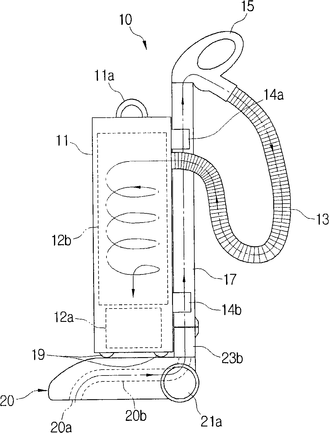
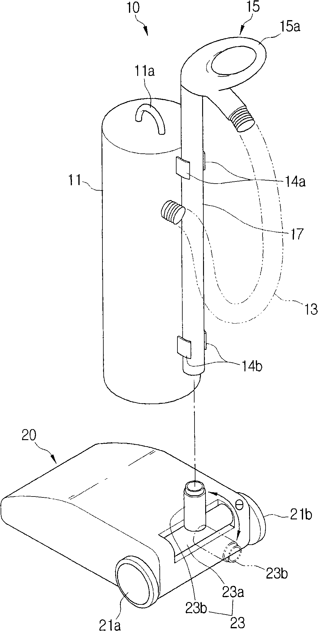
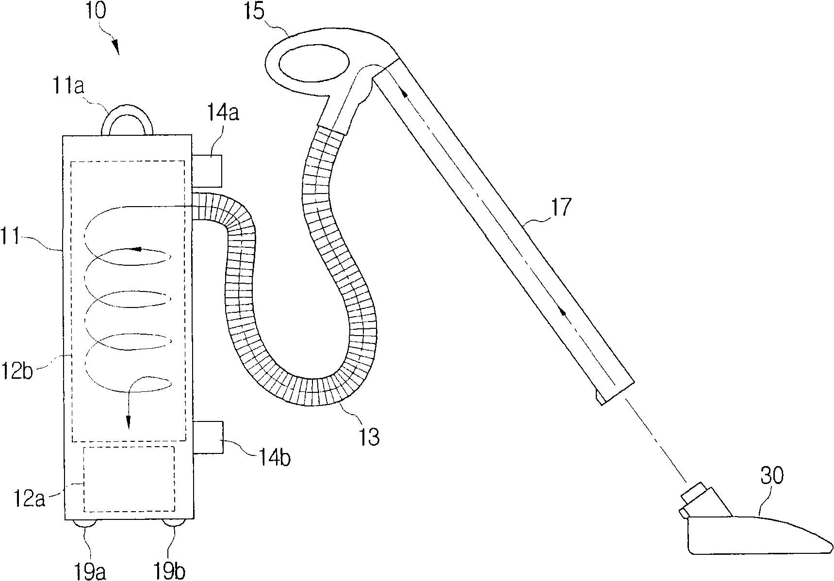
[0037] refer to figure 1 with 2 , the vacuum cleaner according to the first exemplary embodiment of the present invention, which includes a cleaning unit 10 and a suction port assembly 20 . The cleaning unit 10 is detachable from the suction port assembly 20 and used separately.

[0038] The cleaning unit 10 may include a cleaner body 11 , a hose 13 , an operating handle assembly 15 , and an extension pipe 17 .

[0039]The cleaner unit 11 may include a suction motor 12a for generating suction inside the cleaner main body 11; Separat...


PUM


Abstract

A vacuum cleaner operable on upright mode and canister mode is provided. The vacuum cleaner includes a suction port assembly comprising a suction port and a suction passage to draw in dust-laden air, a cleaner body housing a dust separating unit and a motor connected with the dust separating unit, an operating handle assembly in fluid communication with the cleaner body through a hose and in fluid communication with an extension pipe, and a carrying handle assembly sliding along the cleaner body to increase in length. If the vacuum cleaner is in the upright mode, the extension pipe is in fluid communication with the suction port assembly, is used as a passage for air to pass toward the cleaner body, and supports the cleaner body, while if the vacuum cleaner is in the canister mode, the extension pipe is separated from the cleaner body.

Description

[0001] Cross References to Related Applications [0002] This application claims U.S. Patent Application No. 60 / 964676 filed with the United States Patent and Trademark Office on August 14, 2007, and filed with the Korean Intellectual Property Office on September 14, 2007 and August 2, 2007 The priority of Korean Patent Application Nos. 2007-0093884 and Nos. 2007-0077662, the entire disclosure of which is hereby incorporated by reference. technical field [0003] The present invention relates to a vacuum cleaner, and more particularly, to a vacuum cleaner capable of sucking dust-laden air from a surface to be cleaned by using suction generated by a motor driven inside the main body of the cleaner, from the sucked air Dust is filtered in the middle of the vacuum cleaner, and the purified air is discharged to the outside of the main body of the vacuum cleaner. Background technique [0004] Vacuum cleaners can be broadly classified into upright vacuum cleaners and canister vac...

Claims


Application Information

Patent Timeline
Patent Type & Authority Applications(China)
IPC IPC(8): A47L5/32A47L9/02
Inventor 刘东勋朴润姬郑铭淳郑日斗
Owner SAMSUNG GWANGJU ELECTRONICS CO LTD
Why Eureka
Try Eureka